Toyota Venza: Components
COMPONENTS
ILLUSTRATION
ILLUSTRATION
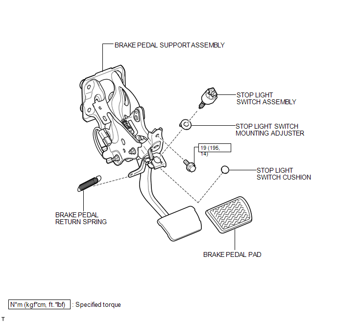
 Brake Pedal
...
 Removal
REMOVAL
PROCEDURE
1. REMOVE BRAKE BOOSTER ASSEMBLY
HINT:
Refer to the instructions for Removal of the brake booster assembly (See page
).
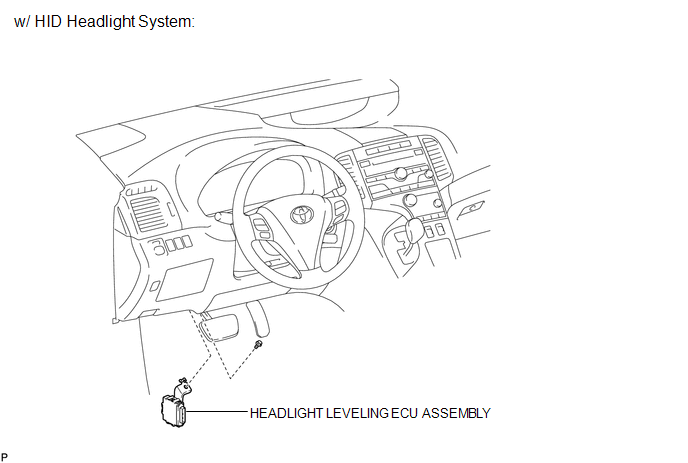
2. REMOVE HEADLIGHT LEVELING ECU ASSEMBLY (w/ HID Headl ...
Other materials about Toyota Venza:
Lost Communication with Rear Gate Module (U0230)
DESCRIPTION
DTC No.
DTC Detection Condition
Trouble Area
U0230
No communication from the power back door ECU (back door motor unit)
or back door closer ECU continues.
Power ...
Atf Temperature Sensor(when Using The Engine Support Bridge)
Components
COMPONENTS
ILLUSTRATION
Inspection
INSPECTION
PROCEDURE
1. INSPECT ATF TEMPERATURE SENSOR ASSEMBLY
(a) Measure the resistance according to the value(s) in the table below.
Standard Resistance:
Tester C ...
System Description
SYSTEM DESCRIPTION
CAUTION:
If using a pacemaker, be sure to read the manual of the pacemaker before using
the key, as the radio waves of the key may affect the pacemaker.
1. SMART KEY SYSTEM DESCRIPTION
(a) In addition to conventional mechanical key and ...

0.1163