Toyota Venza: Components
COMPONENTS
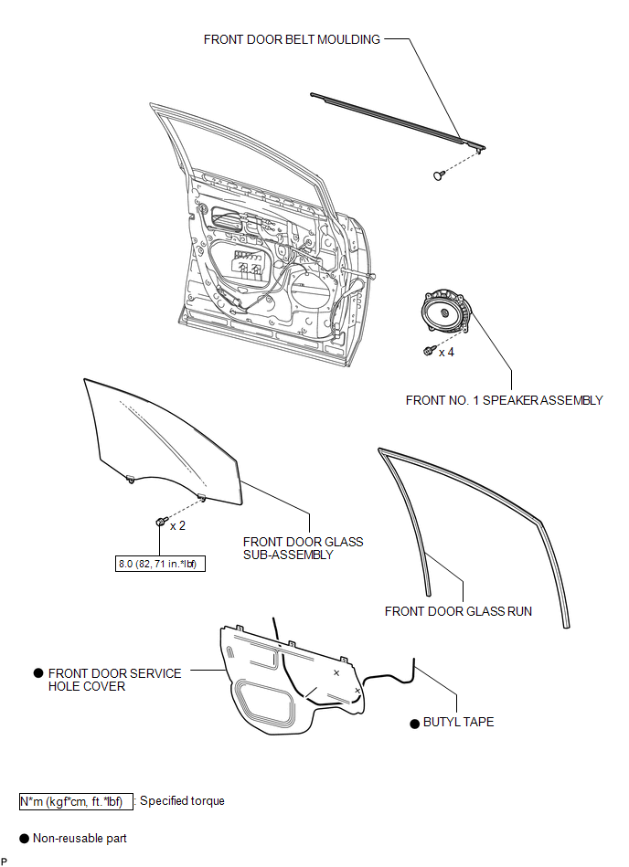
ILLUSTRATION
.png)
ILLUSTRATION

 Installation
INSTALLATION
PROCEDURE
1. INSTALL FRONT DOOR BELT MOULDING
(a) Engage the 5 claws to install the front door belt moulding.
(b) Install the ...
Other materials about Toyota Venza:
Dtc Check / Clear
DTC CHECK / CLEAR
1. CHECK DTC (CHECK USING TECHSTREAM)
(a) Connect the Techstream to the DLC3.
(b) Turn the ignition switch to ON.
(c) Turn the Techstream on.
(d) Enter the following menus: Body Electrical / Navigation System / Trouble
Codes.
(e) Chec ...
Transmission Control Switch Circuit
DESCRIPTION
When the shift lever is in S and it is moved toward "-" or "+", it is possible
to select different shift ranges (1st through 6th ranges).
Moving the shift lever toward "+" increases the shift range by one, and movi ...
Removal
REMOVAL
PROCEDURE
1. DISCONNECT CABLE FROM NEGATIVE BATTERY TERMINAL
NOTICE:
When disconnecting the cable, some systems need to be initialized after the cable
is reconnected (See page ).
2. REMOVE COOL AIR INTAKE DUCT SEAL
3. REMOVE NO. 1 ENGINE CO ...

0.1782