Toyota Venza: Components
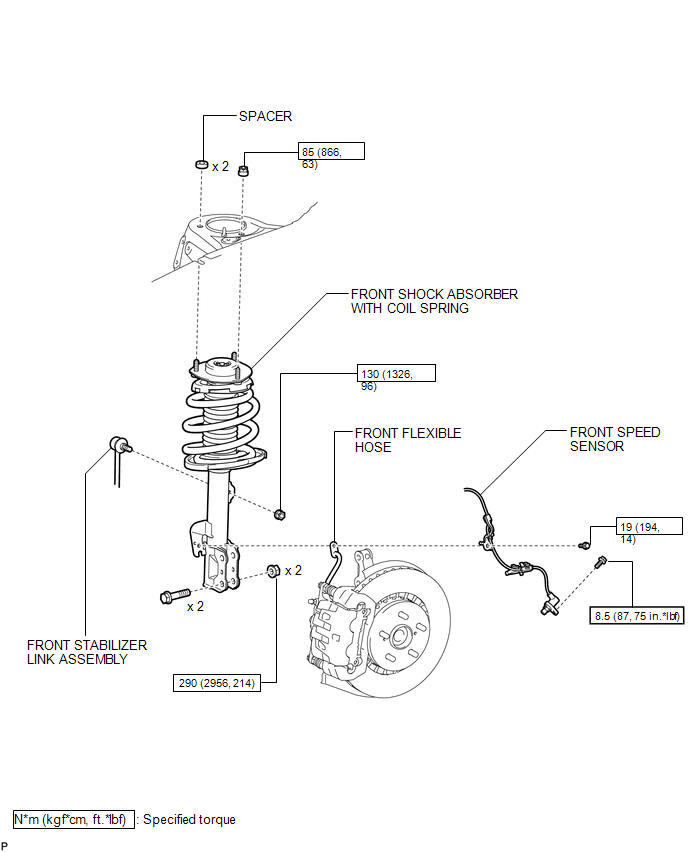
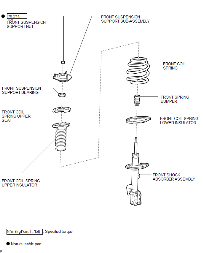
COMPONENTS
ILLUSTRATION
.png)
ILLUSTRATION
ILLUSTRATION

 Removal
REMOVAL
CAUTION / NOTICE / HINT
HINT:
Use the same procedure for the LH side and RH side.
The following procedure listed below is for the LH side.
PROCEDURE
1. REMOVE FRONT WHEE ...
Other materials about Toyota Venza:
Disassembly
DISASSEMBLY
PROCEDURE
1. REMOVE ENGINE COVER JOINT
(a) Remove the 3 joints.
2. REMOVE SPARK PLUG
3. REMOVE CAMSHAFT TIMING OIL CONTROL VALVE ASSEMBLY (for Intake Side)
4. REMOVE CAMSHAFT TIM ...
Installation
INSTALLATION
PROCEDURE
1. INSTALL HEADLIGHT ASSEMBLY
(a) Connect each connector.
(b) Install the headlight assembly with the bolt and 3 screws.
Torque:
3.6 N·m {37 kgf·cm, 32 in·lbf}
2. INSTALL FRONT BUMPER ASSEMBLY
(See page )
3. CONNECT CABLE T ...
Diagnosis System
DIAGNOSIS SYSTEM
1. CHECK BATTERY VOLTAGE
Standard voltage:
11 to 14 V
If the voltage is below 11 V, recharge the battery before proceeding to the next
step.
2. CHECK DLC3
(a) The ECU uses ISO 15765-4 for communication. The terminal arrangement of the ...

0.1568