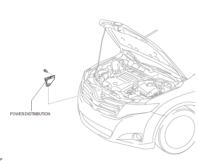
Toyota Venza: Components
COMPONENTS
ILLUSTRATION

 Inspection
INSPECTION
PROCEDURE
1. INSPECT INTEGRATION RELAY
(a) Inner circuit (for 2GR-FE)
(1) for EFI MAIN relay
Measure the resistance according to the value(s) in the table
...
Other materials about Toyota Venza:
Precaution
PRECAUTION
NOTICE:
When disconnecting the cable from the negative (-) battery terminal, initialize
the following systems after the cable is reconnected.
System Name
See Procedure
Back Door Closer System
...
Black Screen
PROCEDURE
1.
CHECK DISPLAY SETTING
(a) Check that the display is not in screen off mode.
OK:
The display setting is not in screen off mode.
NG
CHANGE SCREEN TO SCREEN ON MODE
...
Installation
INSTALLATION
PROCEDURE
1. INSTALL POWER OUTLET SOCKET COVER NO.1
(a) Engage the 2 claws to install the power point socket cover.
2. INSTALL POWER POINT SOCKET ASSEMBLY
(a) Engage the 2 c ...

0.1428