Toyota Venza: Clearance Warning ECU Power Source Circuit
DESCRIPTION
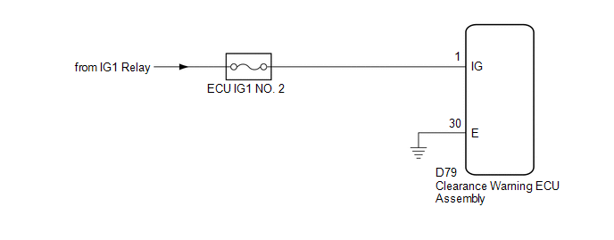
This circuit provides power to operate the clearance warning ECU assembly.
WIRING DIAGRAM
CAUTION / NOTICE / HINT
NOTICE:
Inspect the fuses for circuits related to this system before performing the following inspection procedure.
PROCEDURE
|
1. |
CHECK HARNESS AND CONNECTOR (CLEARANCE WARNING ECU ASSEMBLY POWER SOURCE) |
(a) Disconnect the D79 clearance warning ECU assembly connector.
(b) Measure the voltage according to the value(s) is the table below.
Standard Voltage:
|
Tester Connection |
Condition |
Specified Condition |
|---|---|---|
|
D79-1 (IG) - Body ground |
Engine switch on (IG) |
11 to 14 V |
|
D79-1 (IG) - Body ground |
Engine switch off |
Below 1 V |
| NG | .gif) |
REPAIR OR REPLACE HARNESS OR CONNECTOR |
|
.gif)
|
2. |
CHECK HARNESS AND CONNECTOR (CLEARANCE WARNING ECU ASSEMBLY - BODY GROUND) |
(a) Measure the resistance according to the value(s) in the table below.
Standard Resistance:
|
Tester Connection |
Condition |
Specified Condition |
|---|---|---|
|
D79-30 (E) - Body ground |
Always |
Below 1 Ω |
| OK | |
PROCEED TO NEXT SUSPECTED AREA SHOWN IN PROBLEM SYMPTOMS TABLE |
| NG | |
REPAIR OR REPLACE HARNESS OR CONNECTOR |
 Clearance Warning Buzzer Circuit
DESCRIPTION
This circuit consists of the No. 1 clearance warning buzzer and clearance warning
ECU assembly. An ECU-excited type buzzer is used. The ECU operates the buzzer using
a sound pattern t ...

Other materials about Toyota Venza:
How To Proceed With Troubleshooting
CAUTION / NOTICE / HINT
HINT:
Use the following procedure to troubleshoot the wiper and washer system.
PROCEDURE
1.
VEHICLE BROUGHT TO WORKSHOP
NEXT
...
Audio Receiver Assembly Communication Stop Mode
DESCRIPTION
Detection Item
Symptom
Trouble Area
Audio Receiver Assembly Communication Stop Mode
"Display and Navigation (AVN1)" is not displayed on the "CAN
Bus Check ...
Installation
INSTALLATION
PROCEDURE
1. INSTALL ATF TEMPERATURE SENSOR ASSEMBLY
(a) Coat a new O-ring with ATF and install it to the ATF temperature
sensor assembly.
Text in Illustration
*1
O-ring
...

0.1163