Toyota Venza: Clearance Warning Buzzer Circuit
DESCRIPTION
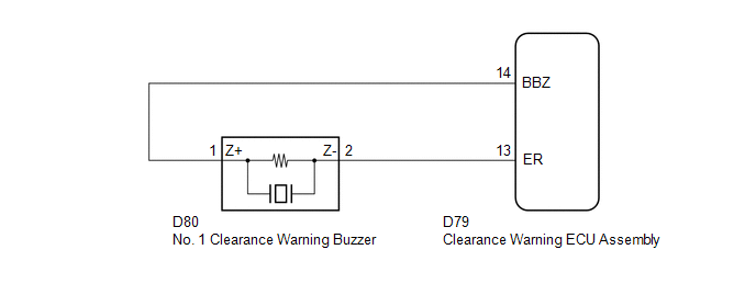
This circuit consists of the No. 1 clearance warning buzzer and clearance warning ECU assembly. An ECU-excited type buzzer is used. The ECU operates the buzzer using a sound pattern that changes depending on the distance to the obstacle.
WIRING DIAGRAM
PROCEDURE
|
1. |
PERFORM ACTIVE TEST USING TECHSTREAM |
(a) Connect the Techstream to the DLC3.
(b) Turn the engine switch on (IG).
(c) Turn the Techstream on.
(d) Enter the following menus: Body Electrical / Intuitive P/A / Active Test.
(e) Check that the buzzer operates by performing the Active Test.
Intuitive P/A|
Tester Display |
Test Part |
Control Range |
Diagnostic Note |
|---|---|---|---|
|
Buzzer |
No. 1 clearance warning buzzer |
Operate or Stop |
Confirm that the vehicle is stopped and the engine switch is on (IG) |
OK:
The No. 1 clearance warning buzzer sounds.
| OK | .gif) |
PROCEED TO NEXT SUSPECTED AREA SHOWN IN PROBLEM SYMPTOMS TABLE |
|
.gif)
|
2. |
CHECK HARNESS AND CONNECTOR (CLEARANCE WARNING ECU ASSEMBLY - NO. 1 CLEARANCE WARNING BUZZER) |
(a) Disconnect the D80 No. 1 clearance warning buzzer connector.
(b) Disconnect the D79 clearance warning ECU assembly connector.
(c) Measure the resistance according to the value(s) in the table below.
Standard Resistance:
|
Tester Connection |
Condition |
Specified Condition |
|---|---|---|
|
D79-14 (BBZ) - D80-1 (Z+) |
Always |
Below 1 Ω |
|
D79-13 (ER) - D80-2 (Z-) |
Always |
Below 1 Ω |
|
D79-14 (BBZ) - Body ground |
Always |
10 kΩ or higher |
|
D79-13 (ER) - Body ground |
Always |
10 kΩ or higher |
| NG | |
REPAIR OR REPLACE HARNESS OR CONNECTOR |
|
|
3. |
REPLACE NO. 1 CLEARANCE WARNING BUZZER |
(a) Replace the No. 1 clearance warning buzzer with a new or known good one (See
page .gif) ).
).
|
|
4. |
PERFORM ACTIVE TEST USING TECHSTREAM |
(a) Connect the Techstream to the DLC3.
(b) Turn the engine switch on (IG).
(c) Turn the Techstream on.
(d) Enter the following menus: Body Electrical / Intuitive P/A / Active Test.
(e) Check that the buzzer operates by performing the Active Test.
Intuitive P/A|
Tester Display |
Test Part |
Control Range |
Diagnostic Note |
|---|---|---|---|
|
Buzzer |
No. 1 clearance warning buzzer |
Operate or Stop |
Confirm that the vehicle is stopped and the engine switch is on (IG) |
OK:
The No. 1 clearance warning buzzer sounds.
| OK | |
END |
| NG | |
REPLACE CLEARANCE WARNING ECU ASSEMBLY |
 Clearance Sonar Main Switch Circuit
DESCRIPTION
The back sonar or clearance sonar switch assembly is installed at the base of
the driver side of the instrument panel.
When the clearance sonar main switch is turned on, an on signal i ...
 Clearance Warning ECU Power Source Circuit
DESCRIPTION
This circuit provides power to operate the clearance warning ECU assembly.
WIRING DIAGRAM
CAUTION / NOTICE / HINT
NOTICE:
Inspect the fuses for circuits related to this system befor ...
Other materials about Toyota Venza:
Speaker Output Short (B15C3)
DESCRIPTION
This DTC is stored when a malfunction occurs in the speakers.
DTC No.
DTC Detection Condition
Trouble Area
B15C3
A short is detected in the speaker output circuit.
...
Ignition Hold Monitor Malfunction (B2271)
DESCRIPTION
This DTC is stored when a problem such as an open in the AM2 fuse, an open or
short in the wire harness between the fuse and power management control ECU, a short
in the IG output circuit inside the power management control ECU, a short betwee ...
Front Passenger Side Door ECU Communication Stop (B2322)
DESCRIPTION
This DTC is stored when LIN communication between the power window regulator
motor assembly (for front passenger side) and main body ECU (driver side junction
block assembly) stops for more than 10 seconds.
DTC No.
DTC D ...

0.1434