Toyota Venza: Clearance Sonar Main Switch
Components
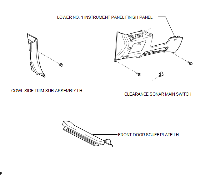
COMPONENTS
ILLUSTRATION
Removal
REMOVAL
PROCEDURE
1. REMOVE FRONT DOOR SCUFF PLATE LH
.gif)
2. REMOVE COWL SIDE TRIM SUB-ASSEMBLY LH
3. REMOVE LOWER NO. 1 INSTRUMENT PANEL FINISH PANEL
4. REMOVE CLEARANCE SONAR MAIN SWITCH
|
(a) Disengage the 2 claws and remove the clearance sonar main switch. |
|

Inspection
INSPECTION
PROCEDURE
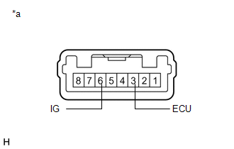
1. INSPECT BACK SONAR OR CLEARANCE SONAR SWITCH ASSEMBLY
|
(a) Measure the resistance according to the value(s) in the table below. Standard Resistance:
If the result is not as specified, replace the back sonar or clearance sonar switch assembly. |
|
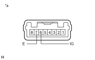
(b) Check that the switch illuminates.
|
(1) Apply battery voltage to the back sonar or clearance sonar switch assembly and check that the switch illuminates. OK:
If the result is not as specified, replace the back sonar or clearance sonar switch assembly. |
|

(c) Check switch indicator operation.
|
(1) Apply battery voltage to the back sonar or clearance sonar switch assembly and check that the switch indicator illuminates. OK:
If the result is not as specified, replace the back sonar or clearance sonar switch assembly. |
|
Installation
INSTALLATION
PROCEDURE
1. INSTALL CLEARANCE SONAR MAIN SWITCH
(a) Engage the 2 claws to install the clearance sonar main switch.
2. INSTALL LOWER NO. 1 INSTRUMENT PANEL FINISH PANEL
.gif)
3. INSTALL COWL SIDE TRIM SUB-ASSEMBLY LH
4. INSTALL FRONT DOOR SCUFF PLATE LH

 Clearance Warning Buzzer
Components
COMPONENTS
ILLUSTRATION
Removal
REMOVAL
PROCEDURE
1. REMOVE FRONT DOOR SCUFF PLATE LH
2. REMOVE COWL SIDE TRIM SUB-ASSEMBLY LH
3. REMOVE LOWER NO. 1 INSTRUMENT PANEL FIN ...
Other materials about Toyota Venza:
Problem Symptoms Table
PROBLEM SYMPTOMS TABLE
HINT:
Use the table below to help determine the cause of problem symptoms. If multiple
suspected areas are listed, the potential causes of the symptoms are listed in order
of probability in the "Suspected Area" column of ...
Removal
REMOVAL
PROCEDURE
1. DISCONNECT CABLE FROM NEGATIVE BATTERY TERMINAL
NOTICE:
When disconnecting the cable, some systems need to be initialized after the cable
is reconnected (See page ).
2. REMOVE NO. 1 ENGINE COVER SUB-ASSEMBLY
3. REMOVE COOL AIR ...
Diagnosis Circuit
DESCRIPTION
The headlight leveling ECU assembly outputs DTC information to the Techstream
via this circuit.
WIRING DIAGRAM
PROCEDURE
1.
CHECK HARNESS AND CONNECTOR (DLC3 - HEADLIGHT LEVELING ECU ASSEMBLY)
(a) Disconnect ...

0.1521