Toyota Venza: Certification Ecu
Components
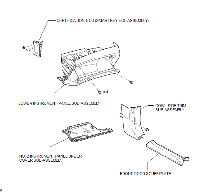
COMPONENTS
ILLUSTRATION
Removal
REMOVAL
PROCEDURE
1. DISCONNECT CABLE FROM NEGATIVE BATTERY TERMINAL
CAUTION:
Wait at least 90 seconds after disconnecting the cable from the negative (-) battery terminal to disable the SRS system.
NOTICE:
When disconnecting the cable, some systems need to be initialized after the cable
is reconnected (See page .gif) ).
).
2. REMOVE FRONT DOOR SCUFF PLATE
HINT:
Use the same procedure for the RH side and LH side (See page
).
3. REMOVE COWL SIDE TRIM SUB-ASSEMBLY
HINT:
Use the same procedure for the RH side and LH side (See page
).
4. REMOVE NO. 2 INSTRUMENT PANEL UNDER COVER SUB-ASSEMBLY
5. REMOVE LOWER INSTRUMENT PANEL SUB-ASSEMBLY
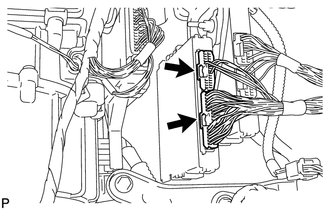
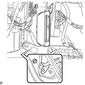
6. REMOVE CERTIFICATION ECU (SMART KEY ECU ASSEMBLY)
|
(a) Disconnect each connector. |
|
|
(b) Remove the 2 nuts and the certification ECU (smart key ECU assembly). |
|
Installation
INSTALLATION
PROCEDURE
1. INSTALL CERTIFICATION ECU (SMART KEY ECU ASSEMBLY)
|
(a) Install the certification ECU (smart key ECU assembly) with the 2 nuts. |
|
.png)
|
(b) Connect each connector. |
|
.png)
2. INSTALL LOWER INSTRUMENT PANEL SUB-ASSEMBLY
.gif)
3. INSTALL NO. 2 INSTRUMENT PANEL UNDER COVER SUB-ASSEMBLY
4. INSTALL COWL SIDE TRIM SUB-ASSEMBLY
HINT:
Use the same procedure for the RH side and LH side (See page
).
5. INSTALL FRONT DOOR SCUFF PLATE
HINT:
Use the same procedure for the RH side and LH side (See page
).
6. CONNECT CABLE TO NEGATIVE BATTERY TERMINAL
NOTICE:
When disconnecting the cable, some systems need to be initialized after the cable
is reconnected (See page ).
7. REGISTER KEY
NOTICE:
When replacing the certification ECU (smart key ECU assembly), perform initialization
(See page ).
8. REGISTER ECU COMMUNICATION ID
NOTICE:
When replacing the certification ECU (smart key ECU assembly), perform initialization
(See page ).

 Electrical Key Oscillator(for Center Floor)
Components
COMPONENTS
ILLUSTRATION
Installation
INSTALLATION
PROCEDURE
1. INSTALL ELECTRICAL KEY OSCILLATOR
(a) Engage the clamp and install the electrical key oscillator.
N ...
Other materials about Toyota Venza:
Headlight Beam Level Control Actuator Circuit
DESCRIPTION
The headlight leveling ECU assembly actuates the headlight leveling motor according
to vehicle conditions.
WIRING DIAGRAM
PROCEDURE
1.
READ VALUE USING TECHSTREAM
(a) Connect the Techstream to the DLC3.
(b) ...
Idle Control System Malfunction (P0505)
DESCRIPTION
The idle speed is controlled by the electronic throttle control system. The electronic
throttle control system is comprised of: 1) the one-valve-type throttle body; 2)
the throttle actuator, which operates the throttle valve; 3) the throttle p ...
Occupant Classification System Malfunction (B1650/32)
DESCRIPTION
The occupant classification system circuit consists of the center airbag sensor
assembly and occupant classification system.
If the center airbag sensor assembly receives signals from the occupant classification
ECU, it determines whether the ...

0.1708