Toyota Venza: Center Power Outlet Socket
Components
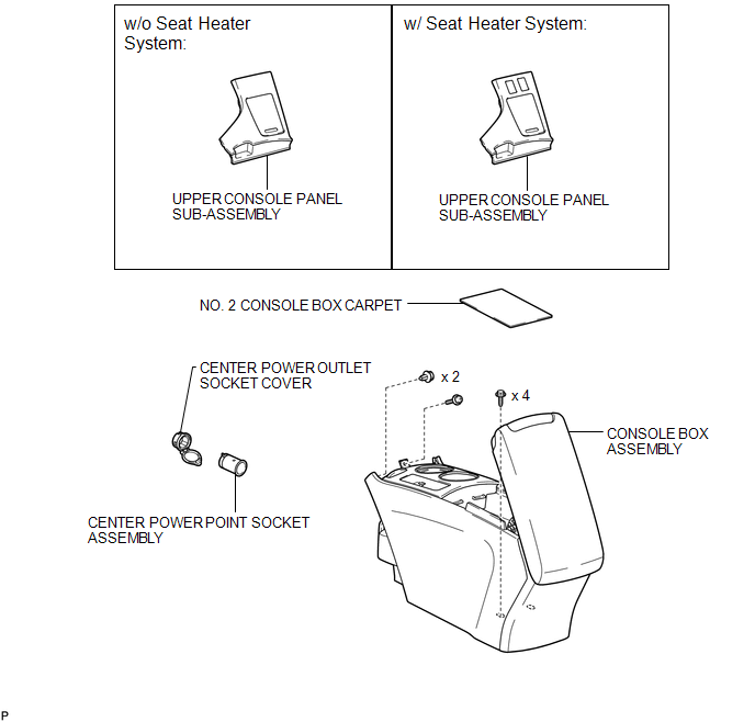
COMPONENTS
ILLUSTRATION
Installation
INSTALLATION
PROCEDURE
1. INSTALL CENTER POWER OUTLET SOCKET COVER
|
(a) Engage the 2 claws to install the center power outlet socket cover. |
|
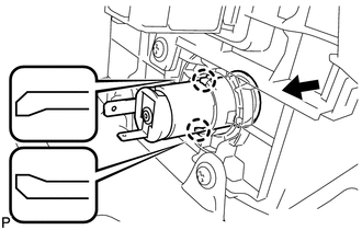
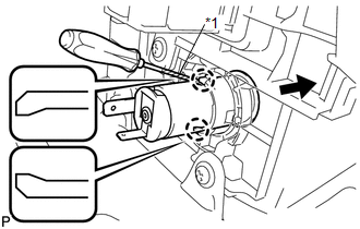
2. INSTALL CENTER POWER POINT SOCKET ASSEMBLY
|
(a) Engage the 2 claws to install the center power point socket assembly as shown in the illustration. |
|
3. INSTALL CONSOLE BOX ASSEMBLY
.gif)
4. INSTALL NO. 2 CONSOLE BOX CARPET
5. INSTALL UPPER CONSOLE PANEL SUB-ASSEMBLY (w/o Seat Heater System)
6. INSTALL UPPER CONSOLE PANEL SUB-ASSEMBLY (w/ Seat Heater System)
Removal
REMOVAL
PROCEDURE
1. REMOVE UPPER CONSOLE PANEL SUB-ASSEMBLY (w/o Seat Heater System)
.gif)
2. REMOVE UPPER CONSOLE PANEL SUB-ASSEMBLY (w/ Seat Heater System)
3. REMOVE NO. 2 CONSOLE BOX CARPET
4. REMOVE CONSOLE BOX ASSEMBLY
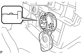
5. REMOVE CENTER POWER POINT SOCKET ASSEMBLY
|
(a) Using a screwdriver, disengage the 2 claws and remove the center power point socket assembly as shown in the illustration. Text in Illustration
HINT: Tape the screwdriver tip before use. |
|
6. REMOVE CENTER POWER OUTLET SOCKET COVER
|
(a) Disengage the 2 claws and remove the center power outlet socket cover. |
|
.png)


Other materials about Toyota Venza:
Front Passenger Side Door Entry Lock and Unlock Functions do not Operate
DESCRIPTION
When the entry lock and unlock functions do not operate only for the front passenger
door, an error in output request codes from the front passenger door or malfunction
in the front door outside handle assembly is suspected. If the entry funct ...
Installation
INSTALLATION
PROCEDURE
1. TEMPORARILY TIGHTEN REAR DISC BRAKE BLEEDER PLUG
(a) Temporarily tighten the rear disc brake bleeder plug.
HINT:
Fully tighten the rear disc brake bleeder plug after bleeding any air left in
the system.
(b) Install the rear di ...
Installation
INSTALLATION
PROCEDURE
1. INSTALL STARTER ASSEMBLY
(a) Install the starter with the 2 bolts.
Torque:
37 N·m {377 kgf·cm, 27 ft·lbf}
(b) Connect the starter connector.
...

0.1594