Toyota Venza: Brake Switch "A" / "B" Correlation (P0504)
DESCRIPTION
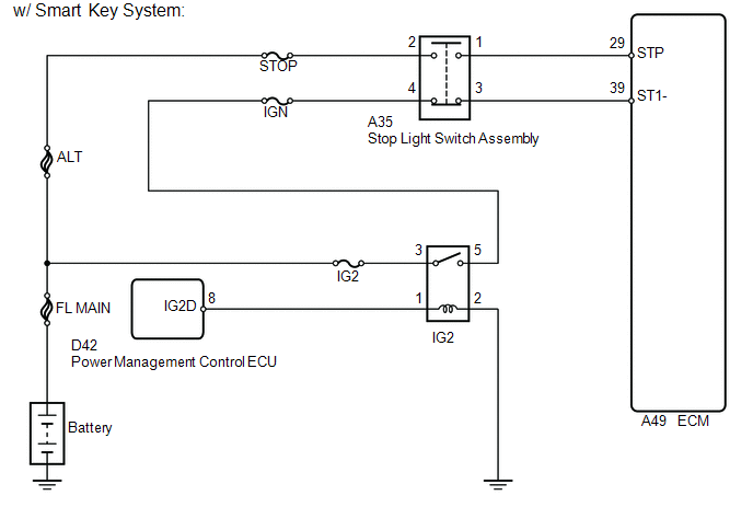
The stop light switch is a duplex system that transmits 2 signals: STP and ST1-. These 2 signals are used by the ECM to monitor whether or not the brake system is working properly. If signals which indicate the brake pedal is being depressed and released are detected simultaneously, the ECM interprets this as a malfunction in the stop light switch and stores the DTC.
HINT:
The normal signal conditions are as shown in the table below.
|
Signal (ECM Terminal) |
Brake Pedal Released |
In Transition |
Brake Pedal Depressed |
|---|---|---|---|
|
STP |
OFF |
ON |
ON |
|
ST1- |
ON |
ON |
OFF |
- [OFF] denotes ground potential.
- [ON] denotes battery potential (+B).
- On the Techstream, both the Data List items Stop Light Switch and ST1 are ON when the brake pedal is depressed because the ST1 indication characteristic is opposite to the Stop Light Switch indication.
|
DTC No. |
DTC Detection Condition |
Trouble Area |
|---|---|---|
|
P0504 |
All of the following conditions continue for 0.5 seconds or more (1 trip detection logic): (a) The ignition switch is ON. (b) The STP signal is OFF when the ST1- signal is OFF. |
|
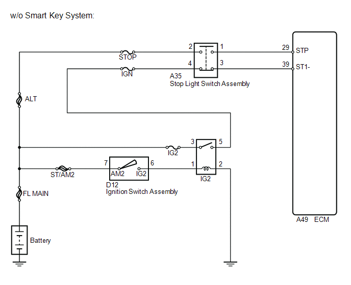
WIRING DIAGRAM
CAUTION / NOTICE / HINT
NOTICE:
Inspect the fuses for circuits related to this system before performing the following inspection procedure.
HINT:
- Read freeze frame data using the Techstream. The ECM records vehicle and driving condition information as freeze frame data the moment a DTC is stored. When troubleshooting, freeze frame data can help determine if the vehicle was moving or stationary, if the engine was warmed up or not, if the air fuel ratio was lean or rich, and other data from the time the malfunction occurred.
- Stop light switch conditions can be checked using the Techstream.
- Connect the Techstream to the DLC3.
- Turn the ignition switch to ON.
- Turn the Techstream on.
- Enter the following menus: Powertrain / Engine / Data List / Stop Light Switch and ST1.
- Check the Data List indication when the brake pedal is depressed and released.
|
Brake Pedal Operation |
Stop Light Switch |
ST1 |
|---|---|---|
|
Depressed |
ON |
ON |
|
Released |
OFF |
OFF |
PROCEDURE
|
1. |
INSPECT STOP LIGHT SWITCH ASSEMBLY (TERMINAL VOLTAGE) |
|
(a) Disconnect the stop light switch assembly connector. |
|
(b) Measure the voltage according to the value(s) in the table below.
Standard Voltage:
|
Tester Connection |
Switch Condition |
Specified Condition |
|---|---|---|
|
A35-2 - Body ground |
Always |
11 to 14 V |
|
A35-4 - Body ground |
Ignition switch ON |
11 to 14 V |
|
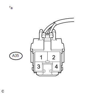
*a |
Front view of wire harness connector (to Stop Light Switch Assembly) |
| NG | .gif) |
REPAIR OR REPLACE HARNESS OR CONNECTOR |
|
.gif)
|
2. |
INSPECT STOP LIGHT SWITCH ASSEMBLY |
(a) Inspect the stop light switch assembly (See page
.gif) ).
).
| NG | |
REPLACE STOP LIGHT SWITCH ASSEMBLY |
|
|
3. |
INSPECT ECM (STP AND ST1- VOLTAGE) |
(a) Disconnect the ECM connector.
(b) Turn the ignition switch to ON.
(c) Measure the voltage according to the value(s) in the table below.
Standard Voltage:
|
Tester Connection |
Condition |
Specified Condition |
|---|---|---|
|
A49-39 (ST1-) - Body ground |
Brake pedal released |
7.5 to 14 V |
|
Brake pedal depressed |
Below 1.5 V |
|
|
A49-29 (STP) - Body ground |
Brake pedal released |
Below 1.5 V |
|
Brake pedal depressed |
7.5 to 14 V |
|
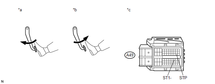
*a |
Brake pedal depressed |
*b |
Brake pedal released |
|
*c |
Front view of wire harness connector (to ECM) |
- |
- |
| OK | |
REPLACE ECM |
| NG | |
REPAIR OR REPLACE HARNESS OR CONNECTOR |
 Vehicle Speed Sensor "A" (P0500)
DESCRIPTION
The speed sensor detects the wheel speed and sends the appropriate signals to
the skid control ECU.
The skid control ECU converts these wheel speed signals into a 4-pulse signal
and ...
 Idle Control System Malfunction (P0505)
DESCRIPTION
The idle speed is controlled by the electronic throttle control system. The electronic
throttle control system is comprised of: 1) the one-valve-type throttle body; 2)
the throttle ac ...
Other materials about Toyota Venza:
Terminals Of Ecu
TERMINALS OF ECU
1. CHECK POWER BACK DOOR ECU (POWER BACK DOOR MOTOR UNIT)
(a) Disconnect the L20 ECU connector.
(b) Measure the voltage and resistance according to the value(s) in the table
below.
Tester Connection
Wiring Color
...
Camshaft Position "A" - Timing Over-Advanced or System Performance (Bank 1)
(P0011,P0012)
DESCRIPTION
Refer to DTC P0010 (See page ).
DTC No.
DTC Detection Condition
Trouble Area
P0011
The valve timing is stuck at a certain value when in the advance range
(1 trip detection logic).
...
Removal
REMOVAL
PROCEDURE
1. DISCONNECT CABLE FROM NEGATIVE BATTERY TERMINAL
CAUTION:
Wait at least 90 seconds after disconnecting the cable from the negative (-)
battery terminal to disable the SRS system.
NOTICE:
When disconnecting the cable, some systems ne ...

0.1138