Toyota Venza: Brake Pedal Load Sensing Switch
On-vehicle Inspection
ON-VEHICLE INSPECTION
PROCEDURE
1. INSPECT BRAKE PEDAL LOAD SENSING SWITCH
NOTICE:
- Do not remove the brake pedal load sensing switch from the brake pedal support assembly.
- When there is a malfunction in the brake pedal load sensing switch, replace the brake pedal support assembly.
(a) Disconnect the brake pedal load sensing switch connector.
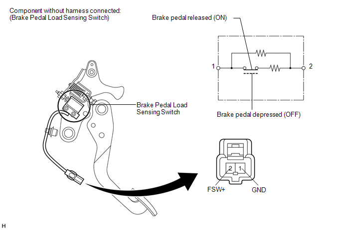
(b) Measure the resistance according to the value(s) in the table below.
Standard Resistance:
|
Tester Connection |
Condition |
Specified Condition |
|---|---|---|
|
2 (FSW+) - 1 (GND) |
Brake pedal load sensing switch OFF (Brake pedal depressed) |
950 to 1050 Ω |
|
2 (FSW+) - 1 (GND) |
Brake pedal load sensing switch ON (Brake pedal released) |
203 to 223 Ω |
If the value is not as specified, replace the brake pedal support assembly (See
page .gif) ).
).
 Installation
INSTALLATION
PROCEDURE
1. INSTALL BRAKE ACTUATOR ASSEMBLY
(a) Install the brake actuator assembly to the brake actuator bracket
assembly with the 2 nuts.
Torque:
8.0 N·m {82 ...

Other materials about Toyota Venza:
Lost Communication with Front Airbag Sensor LH (B1617/84,B1618/84)
DESCRIPTION
The front airbag sensor LH circuit consists of the center airbag sensor assembly
and front airbag sensor LH.
The front airbag sensor LH detects impacts to the vehicle and sends signals to
the center airbag sensor assembly to determine if the ...
Engine does not Start
DESCRIPTION
1. ENGINE START SYSTEM FUNCTION
(a) If the engine switch is pressed with the shift lever in P or N and the brake
pedal depressed, the power management control ECU determines that this is an engine
start request.
(b) The certification ECU (sm ...
Engine Immobiliser System Malfunction (B2799)
DESCRIPTION
This DTC is stored when one of the following occurs: 1) the ECM detects an error
in its own communication with the certification ECU (smart key ECU assembly); 2)
the ECM detects an error in the communication lines; or 3) the ECU communication ...

0.1135