Toyota Venza: Back-up Power Source Circuit
DESCRIPTION
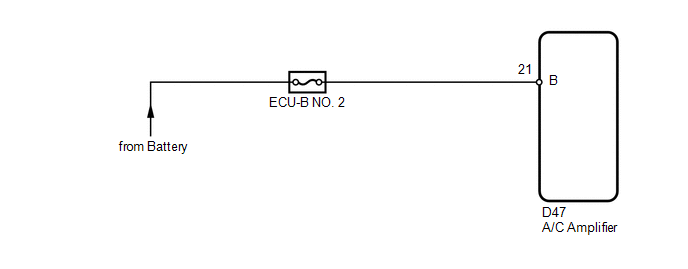
The back-up power source circuit for the A/C amplifier is shown below. Power is supplied even when the ignition switch is turned off. The power is used for diagnostic trouble code memory, etc.
WIRING DIAGRAM
CAUTION / NOTICE / HINT
NOTICE:
Inspect the fuses for circuits related to this system before performing the following inspection procedure.
PROCEDURE
|
1. |
CHECK HARNESS AND CONNECTOR (A/C AMPLIFIER - BATTERY) |
|
(a) Disconnect the A/C amplifier connector. |
|
(b) Measure the voltage according to the value(s) in the table below.
Standard Voltage:
|
Tester Connection |
Condition |
Specified Condition |
|---|---|---|
|
D47-21 (B) - Body ground |
Always |
11 to 14 V |
|
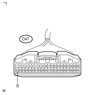
*1 |
Front view of wire harness connector (to A/C Amplifier) |
| OK | .gif) |
PROCEED TO NEXT SUSPECTED AREA SHOWN IN PROBLEM SYMPTOMS TABLE |
| NG | |
REPAIR OR REPLACE HARNESS OR CONNECTOR |
 IG Power Source Circuit
DESCRIPTION
The main power source is supplied to the A/C amplifier when the ignition switch
is ON.
The power source is used for operating the A/C amplifier and servo motor, etc.
WIRING DIAGRAM
...

Other materials about Toyota Venza:
Diagnostic Trouble Code Chart
DIAGNOSTIC TROUBLE CODE CHART
HINT:
If a trouble code is displayed during the DTC check, inspect the trouble areas
listed for that code. For details of the code, refer to the "See page" below.
Power Steering System
DTC Code
...
Remote Up / Down Function does not Operate
DESCRIPTION
When the ignition switch is ON, the power window regulator master switch assembly
sends remote up/down signals to each power window regulator motor assembly via the
LIN communication line.
WIRING DIAGRAM
CAUTION / NOTICE / HINT
NOTICE:
T ...
Noise Occurs
PROCEDURE
1.
CHECK NOISE CONDITION
(a) Check from which direction the noise comes (front left or right, or rear
left or right).
OK:
The location of the noise source can be determined.
NG
GO TO STEP 3
...

0.1424