Toyota Venza: Back Door Opener Switch
Components
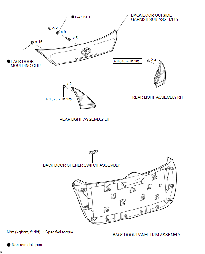
COMPONENTS
ILLUSTRATION
Removal
REMOVAL
PROCEDURE
1. REMOVE BACK DOOR PANEL TRIM ASSEMBLY
.gif)
2. REMOVE REAR LIGHT ASSEMBLY LH
3. REMOVE REAR LIGHT ASSEMBLY RH
HINT:
Use the same procedure for the RH side and LH side.
4. REMOVE BACK DOOR OUTSIDE GARNISH SUB-ASSEMBLY
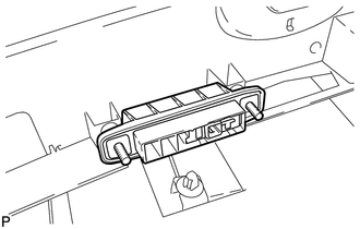
5. REMOVE BACK DOOR OPENER SWITCH ASSEMBLY
|
(a) Remove the back door opener switch assembly. |
|
Inspection
INSPECTION
PROCEDURE
1. INSPECT BACK DOOR OPENER SWITCH ASSEMBLY
(a) Check operation of the opener switch.
(1) Measure the resistance according to the value(s) in the table below.
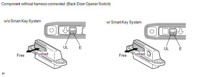
Standard resistance:
|
Tester Connection |
Switch Position |
Specified Condition |
|---|---|---|
|
2(E) - 3(UL) |
Back door opener switch not pushed (OFF) |
10 kΩ or higher |
|
2(E) - 3(UL) |
Back door opener switch pushed (ON) |
Below 1 Ω |
If the result is not specified, replace the back door opener switch assembly.
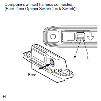
(b) Check operation of the lock switch (w/ Smart Key System).
|
(1) Measure the resistance according to the value(s) in the table below. Standard resistance:
If the result is not specified, replace the back door opener switch assembly. |
|
Installation
INSTALLATION
PROCEDURE
1. INSTALL BACK DOOR OPENER SWITCH ASSEMBLY
|
(a) Install the back door opener switch assembly. |
|
.png)
2. INSTALL BACK DOOR OUTSIDE GARNISH SUB-ASSEMBLY
.gif)
3. INSTALL REAR LIGHT ASSEMBLY LH
4. INSTALL REAR LIGHT ASSEMBLY RH
HINT:
Use the same procedure for the RH side and LH side.
5. INSTALL BACK DOOR PANEL TRIM ASSEMBLY
 Back Door Closer does not Operate
DESCRIPTION
When the back door closer does not operate, one of the following may be the cause:
1) improper fit of the back door, or a foreign object is stuck in the back door
or 2) initialization ...
 Back Door Support
Components
COMPONENTS
ILLUSTRATION
Removal
REMOVAL
PROCEDURE
1. REMOVE BACK DOOR STAY ASSEMBLY
NOTICE:
Avoid touching the piston rod as much as possible to prevent foreign
ma ...
Other materials about Toyota Venza:
Installation
INSTALLATION
PROCEDURE
1. INSTALL FRONT DRIVE SHAFT ASSEMBLY LH
(a) Align the splines of the shaft and install the drive shaft assembly
LH using a brass bar and a hammer.
NOTICE:
Set the shaft snap ring with the opening fac ...
On-vehicle Inspection
ON-VEHICLE INSPECTION
CAUTION / NOTICE / HINT
CAUTION:
Be sure to follow the correct removal and installation procedures of the front
airbag sensor.
PROCEDURE
1. INSPECT FRONT AIRBAG SENSOR (VEHICLE NOT INVOLVED IN COLLISION)
(a) Perform a diagnostic s ...
Fail-safe Chart
FAIL-SAFE CHART
1. FAIL-SAFE OPERATION
If there is a problem with sensor signals or actuator systems, the skid
control ECU prohibits power supply to the brake actuator assembly and informs
the ECM of VSC system malfunction.
The brake actuat ...

0.1283