Toyota Venza: Back Door Lock
Components
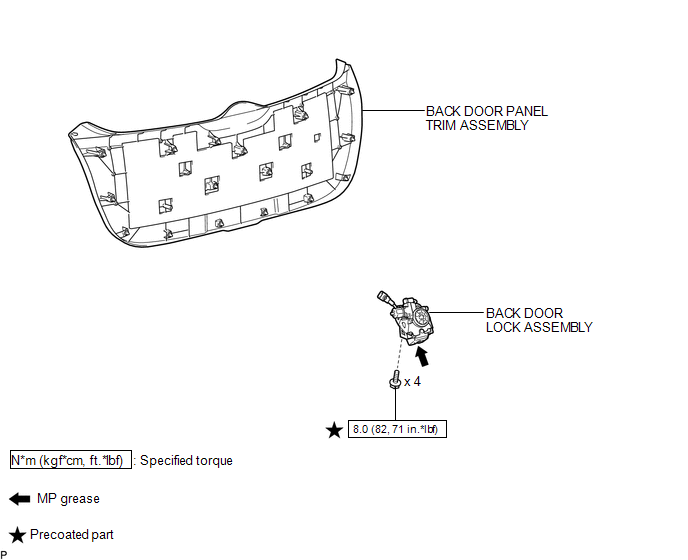
COMPONENTS
ILLUSTRATION
Removal
REMOVAL
PROCEDURE
1. REMOVE BACK DOOR PANEL TRIM ASSEMBLY
.gif)
2. REMOVE BACK DOOR LOCK ASSEMBLY
|
(a) Disconnect the connector. |
|
.png)
(b) Disengage the clamp.
(c) Remove the bolt.
|
(d) Remove the 3 bolts and back door lock assembly. |
|
.png)
Inspection
INSPECTION
PROCEDURE
1. INSPECT BACK DOOR LOCK ASSEMBLY
(a) Check the operation of the door lock motor.
.png)
(1) Apply the battery voltage to the door lock motor and check the operation of the door lock motor.
OK:
|
Measurement Condition |
Specified Condition |
|---|---|
|
Battery positive (+) → Terminal 1 (M+) Battery negative (-) → Terminal 2 (M-) |
Latch turns to full-latch position |
|
Battery positive (+) → Terminal 2 (M-) Battery negative (-) → Terminal 1 (M+) |
Latch turns to open-latch position |
If the result is not specified, replace the back door lock.
(b) Check the operation of the switch.
(1) Measure the resistance according to the value(s) in the table below.
Standard Resistance:
Latch Switch
|
Tester Connection |
Door Lock Latch Position |
Specified Condition |
|---|---|---|
|
5 (ULSW) - 4 (E) |
Open-latch |
Below 1 Ω |
|
5 (ULSW) - 4 (E) |
Half-latch |
10 kΩ or higher |
|
5 (ULSW) - 4 (E) |
Full-latch |
10 kΩ or higher |
|
5 (ULSW) - 4 (E) |
Over-latch |
Below 1 Ω |
Sector Switch
|
Tester Connection |
Condition |
Specified Condition |
|---|---|---|
|
6 (DLSW) - 4 (E) |
Sector gear in neutral position (Sector switch on) |
Below 1 Ω |
|
6 (DLSW) - 4 (E) |
Sector gear not in neutral position (Sector switch off) |
10 kΩ or higher |
Back Door Courtesy Light Switch
|
Tester Connection |
Door Lock Latch Position |
Specified Condition |
|---|---|---|
|
3 (CTY) - 4 (E) |
Open-latch |
Below 1 Ω |
|
3 (CTY) - 4 (E) |
Half-latch |
Below 1 Ω |
|
3 (CTY) - 4 (E) |
Full-latch |
10 kΩ or higher |
|
3 (CTY) - 4 (E) |
Over-latch |
10 kΩ or higher |
If the result is not specified, replace the back door lock assembly.
Installation
INSTALLATION
PROCEDURE
1. INSTALL BACK DOOR LOCK ASSEMBLY
(a) Apply MP grease to the sliding parts of the back door lock assembly.
(b) Apply adhesive to the threads of the bolt.
Adhesive:
Toyota Genuine Adhesive 1324, Three Bond 1324 or equivalent
|
(c) Install the back door lock assembly with the 3 bolts. Torque: 8.0 N·m {82 kgf·cm, 71 in·lbf} |
|
.png)
|
(d) Install the bolt. Torque: 8.0 N·m {82 kgf·cm, 71 in·lbf} |
|
.png)
(e) Engage the clamp.
(f) Connect the connector.
2. INSTALL BACK DOOR PANEL TRIM ASSEMBLY
.gif)
 Door Lock
...

Other materials about Toyota Venza:
Speedometer Malfunction
DESCRIPTION
The meter CPU receives vehicle speed signals from the skid control ECU via the
CAN communication system (CAN No. 1 Bus). The speed sensor detects the wheel speed
and sends the appropriate signals to the skid control ECU. The skid control ECU
...
Installation
INSTALLATION
PROCEDURE
1. INSTALL DISCHARGE HEADLIGHT BULB
HINT:
Use the same procedure for the RH side and LH side (See page
).
2. INSTALL LIGHT CONTROL ECU (for LH Side)
(a) Turn the socket of the light control ECU in the direction indicat ...
How To Proceed With Troubleshooting
CAUTION / NOTICE / HINT
HINT:
Use the following procedure to troubleshoot the power steering system.
*: Use the Techstream.
PROCEDURE
1.
VEHICLE BROUGHT TO WORKSHOP
NEXT
...

0.1507