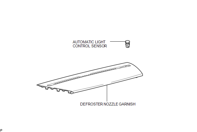
Toyota Venza: Automatic Light Control Sensor
Components
COMPONENTS
ILLUSTRATION
Removal
REMOVAL
PROCEDURE
1. REMOVE DEFROSTER NOZZLE GARNISH
.gif)
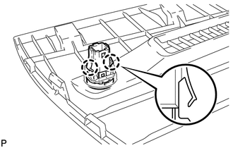
2. REMOVE AUTOMATIC LIGHT CONTROL SENSOR
|
(a) Disengage the 2 claws and remove the automatic light control sensor. |
|
Inspection
INSPECTION
PROCEDURE
1. INSPECT AUTOMATIC LIGHT CONTROL SENSOR
|
(a) Disconnect the F4 automatic light control sensor connector. |
|
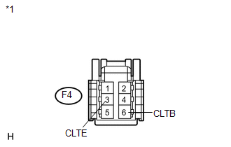
(b) Measure the voltage and resistance according to the value(s) in the table below.
Standard Voltage:
|
Tester Connection |
Condition |
Specified Condition |
|---|---|---|
|
F4-6 (CLTB) - F4-3 (CLTE) |
Ignition switch off |
Below 1 V |
|
Ignition switch ON |
10 to 14 V |
Standard Resistance:
|
Tester Connection |
Condition |
Specified Condition |
|---|---|---|
|
F4-3 (CLTE) - Body ground |
Always |
Below 1 Ω |
|
*1 |
Front view of wire harness connector (to Automatic Light Control Sensor) |
If the result is not as specified, there may be a malfunction on the wire harness side.
|
(c) Reconnect the F4 automatic light control sensor connector. |
|
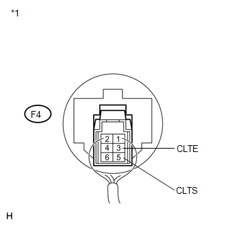
(d) Connect an oscilloscope to the automatic light control sensor connector.
Text in Illustration|
*1 |
Component with harness connected (Automatic Light Control Sensor) |
|
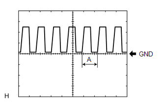
(e) Check the waveform. OK:
HINT: If the ambient light becomes brighter, width A becomes narrower. If the result is not as specified, replace the automatic light control sensor. |
|
Installation
INSTALLATION
PROCEDURE
1. INSTALL AUTOMATIC LIGHT CONTROL SENSOR
|
(a) Engage the 2 claws to install the automatic light control sensor. |
|
.png)
2. INSTALL DEFROSTER NOZZLE GARNISH
.gif)
 Afs Ecu
Components
COMPONENTS
ILLUSTRATION
Installation
INSTALLATION
PROCEDURE
1. INSTALL AFS ECU
(a) Engage the guide.
(b) Install the ...
 Door Mirror Foot Light
Components
COMPONENTS
ILLUSTRATION
Removal
REMOVAL
CAUTION / NOTICE / HINT
HINT:
Use the same procedure for both the RH and LH sides.
The procedure described below is for the ...
Other materials about Toyota Venza:
Engine Circuit Malfunction (C1280/82)
DESCRIPTION
If a malfunction in the ECM circuit occurs, the AWD control ECU will output this
DTC.
DTC No.
DTC Detection Condition
Trouble Area
C1280/82
When the following continues for ...
If a warning message is displayed
The multi-information display shows warnings of system malfunctions or incorrectly
performed operations. When a message is shown, perform corrections as indicated
in the message.
1. Master warning light
The master warning light comes on or flashes when ...
Removal
REMOVAL
CAUTION / NOTICE / HINT
HINT:
Use the same procedure for the RH side and LH side.
The procedure listed below is for the LH side.
PROCEDURE
1. REMOVE FRONT WHEEL
2. REMOVE FRONT AXLE SHAFT NUT
3. SEPARATE FRONT SPEED SENSOR
...

0.1566