Toyota Venza: Automatic door locking and unlocking systems
The following functions can be set or canceled:
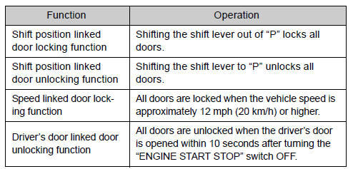
- Setting and canceling the functions
► Setting and canceling the functions Vehicles with TFT type multi-information display The function settings can be changed using the multi-information display.
► Vehicles with LCD type multi-information display To switch between setting and canceling, follow the procedure below:
 Vehicles with smart key system:
Close all the doors and switch the “ENGINE START STOP” switch to IGNITION ON
mode. (Perform  within 20 seconds.)
Vehicles without smart key system:
Close all the doors and switch the engine switch to the “ON” position. (Perform
within 20 seconds.)
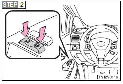
Shift the shift lever to “P” or “N”, press and hold the driver’s door lock switch
(  or
or
 ) for about 5 seconds then release.
The shift lever and switch positions corresponding to the desired function to be set are shown as follows.
Use the same procedure to cancel the function.
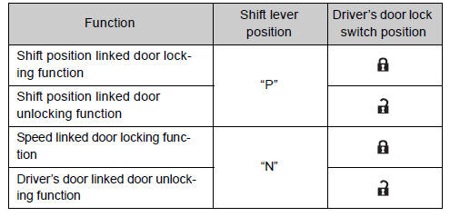
When the setting or canceling operation is complete, all doors are locked and then unlocked.
- Impact detection door lock release system
In the event that the vehicle is subject to a strong impact, all the doors are unlocked.
Depending on the force of the impact or the type of accident, however, the system may not operate.
- Customization
Settings (e.g. unlocking function using a key) can be changed.
(Customizable features )
CAUTION
- To prevent an accident Observe the following precautions while driving the vehicle.
Failing to do so may result in a door opening and an occupant falling out, resulting in death or serious injury.
• Always use a seat belt.
• Always lock all doors.
• Ensure that all doors are properly closed.
• Do not pull the inside handle of the doors while driving.
The doors may be opened and the passengers are thrown out of the vehicle and it may result in death or serious injury.
Be especially careful for the front doors, as the doors may be opened even if the inside lock buttons are in locked position.
• Set the rear door child-protector locks when children are seated in the rear seat.
 Rear door child-protector lock
The door cannot be opened from inside the vehicle when the lock is set.
1. Unlock
2. Lock
These locks can be set to prevent children from opening the rear doors. Push
down on each rear door swi ...
 Back door
The back door can be opened using the back door opener. The back door can
be locked and unlocked using the entry function (vehicles with smart key system),
wireless remote control or door lock swi ...
Other materials about Toyota Venza:
Heated Oxygen Sensor
Components
COMPONENTS
ILLUSTRATION
Removal
REMOVAL
PROCEDURE
1. REMOVE NO. 1 ENGINE UNDER COVER
2. REMOVE NO. 2 ENGINE UNDER COVER
3. REMOVE FRONT EXHAUST PIPE ASSEMBLY
4. REMOVE HEATED OXYGEN SENSOR
(a) Using SST, remove the heat ...
Display does not Dim when Light Control Switch is Turned ON
PROCEDURE
1.
CHECK IMAGE QUALITY SETTING
(a) Turn the light control switch to the tail or head position.
(b) Check that the daytime screen setting on the display adjustment screen is
set to on.
Result
...
Inspection
INSPECTION
PROCEDURE
1. INSPECT CYLINDER HEAD SUB-ASSEMBLY
(a) Using a precision straightedge and feeler gauge, measure the warpage of the
contact surfaces where the cylinder head contacts the cylinder block and manifold.
Maximum Warpage:
...

0.154