Toyota Venza: Ambient Temperature Sensor Circuit (B1412/12)
DESCRIPTION
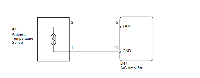
The ambient temperature sensor is installed in front of the condenser. It detects the ambient temperature to control air conditioning AUTO mode. This sensor is connected to the A/C amplifier and detects fluctuations in the ambient temperature. This data is used for controlling the cabin temperature. The sensor sends a signal to the A/C amplifier. The resistance of the ambient temperature sensor changes in accordance with the ambient temperature. As the temperature decreases, the resistance increases. As the temperature increases, the resistance decreases.
The A/C amplifier applies voltage (5 V) to the ambient temperature sensor and reads voltage changes as the resistance of the ambient temperature sensor changes.
|
DTC No. |
DTC Detection Condition |
Trouble Area |
|---|---|---|
|
B1412/12 |
Open or short in ambient temperature sensor circuit |
|
WIRING DIAGRAM
PROCEDURE
|
1. |
READ VALUE USING TECHSTREAM |
(a) Connect the Techstream to the DLC3.
(b) Turn the ignition switch to ON.
(c) Turn the Techstream on.
(d) Enter the following menus: Body / Air Conditioner / Data List.
(e) Check the value(s) by referring to the table below.
Air Conditioner|
Tester Display |
Measurement Item/Range |
Normal Condition |
Diagnostic Note |
|---|---|---|---|
|
Ambient Temp Sensor |
Ambient temperature sensor / Min: -23.3°C (-9.94°F) Max: 65.95°C (150.71°F) |
Actual ambient temperature displayed |
- |
OK:
The display is as specified in the Normal Condition column.
|
Result |
Proceed to |
|---|---|
|
NG |
A |
|
OK (When troubleshooting according to Problem Symptoms Table) |
B |
|
OK (When troubleshooting according to the DTC) |
C |
| B | .gif) |
PROCEED TO NEXT SUSPECTED AREA SHOWN IN PROBLEM SYMPTOMS TABLE |
| C | |
REPLACE A/C AMPLIFIER |
|
.gif)
|
2. |
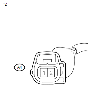
INSPECT AMBIENT TEMPERATURE SENSOR |
(a) Remove the ambient temperature sensor.
(b) Disconnect the ambient temperature sensor connector.
(c) Measure the resistance according to the value(s) in the table below.
Standard Resistance:
|
Tester Connection |
Condition |
Specified Condition |
|---|---|---|
|
A4-1 - A4-2 |
10°C (50°F) |
3.00 to 3.73 kΩ |
|
A4-1 - A4-2 |
15°C (59°F) |
2.45 to 2.88 kΩ |
|
A4-1 - A4-2 |
20°C (68°F) |
1.95 to 2.30 kΩ |
|
A4-1 - A4-2 |
25°C (77°F) |
1.60 to 1.80 kΩ |
|
A4-1 - A4-2 |
30°C (86°F) |
1.28 to 1.47 kΩ |
|
A4-1 - A4-2 |
35°C (95°F) |
1.00 to 1.22 kΩ |
|
A4-1 - A4-2 |
40°C (104°F) |
0.80 to 1.00 kΩ |
|
A4-1 - A4-2 |
45°C (113°F) |
0.65 to 0.85 kΩ |
|
A4-1 - A4-2 |
50°C (122°F) |
0.50 to 0.70 kΩ |
|
A4-1 - A4-2 |
55°C (131°F) |
0.44 to 0.60 kΩ |
|
A4-1 - A4-2 |
60°C (140°F) |
0.36 to 0.50 kΩ |
NOTICE:
- Hold the sensor only by its connector. Touching the sensor may change the resistance value.
- When measuring, the sensor temperature must be the same as the ambient temperature.
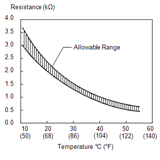
HINT:
As the temperature increases, the resistance decreases (see the graph).
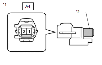
Text in Illustration|
*1 |
Component without harness connected (Ambient Temperature Sensor) |
|
*2 |
Sensing Portion |
| NG | |
REPLACE AMBIENT TEMPERATURE SENSOR |
|
|
3. |
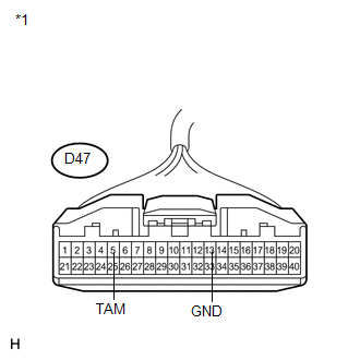
CHECK HARNESS AND CONNECTOR (AMBIENT TEMPERATURE SENSOR - A/C AMPLIFIER) |
|
(a) Disconnect the A/C amplifier connector. |
|
|
(b) Measure the resistance according to the value(s) in the table below. Standard Resistance:
|
|
| OK | |
REPLACE A/C AMPLIFIER |
| NG | |
REPAIR OR REPLACE HARNESS OR CONNECTOR |
 Room Temperature Sensor Circuit (B1411/11)
DESCRIPTION
The room temperature sensor is installed in the instrument panel. It detects
the cabin temperature to control the air conditioning AUTO mode. The resistance
of the room temperature se ...
 Air Conditioning Control Panel Circuit
DESCRIPTION
This circuit consists of the air conditioning control assembly and the A/C amplifier.
When the air conditioning control assembly is operated, signals are transmitted
to the A/C amplif ...
Other materials about Toyota Venza:
Problem Symptoms Table
PROBLEM SYMPTOMS TABLE
Use the table below to help determine the cause of problem symptoms. If multiple
suspected areas are listed, the potential causes of the symptoms are listed in order
of probability in the "Suspected Area" column of the tab ...
Blower Motor Circuit
DESCRIPTION
The blower motor is operated by signals from the A/C amplifier. Blower motor
speed signals are transmitted in accordance with changes in the duty ratio.
WIRING DIAGRAM
CAUTION / NOTICE / HINT
NOTICE:
Inspect the fuses for circuits related ...
Customize Parameters
CUSTOMIZE PARAMETERS
1. CUSTOMIZING FUNCTION WITH TECHSTREAM
HINT:
The following items can be customized.
NOTICE:
When the customer requests a change in a function, first make sure that
the function can be customized.
Be sure to make a not ...

0.1307