Toyota Venza: All Doors LOCK/UNLOCK Functions do not Operate Via Door Control Switch
DESCRIPTION
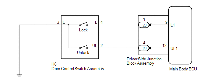
The main body ECU (driver side junction block assembly) receives switch signals from the door control switch and activates the door lock motor on each door according to these signals.
WIRING DIAGRAM
PROCEDURE
|
1. |
READ VALUE USING TECHSTREAM (DOOR CONTROL SWITCH) |
(a) Connect the Techstream to the DLC3.
(b) Turn the ignition switch to ON.
(c) Turn the Techstream on.
(d) Enter the following menus: Body Electrical / Main Body / Data List.
(e) Read the Data List according to the display on the Techstream.
Main Body (Main Body ECU (Driver Side Junction Block Assembly))|
Tester Display |
Measurement Item/Range |
Normal Condition |
Diagnostic Note |
|---|---|---|---|
|
Door Lock SW-Lock |
Front passenger side door control switch lock signal/ON or OFF |
ON: Front passenger side door control switch pushed to lock position OFF: Front passenger side door control switch not pushed to lock position |
- |
|
Door Lock SW-Unlock |
Front passenger side door control switch unlock signal/ON or OFF |
ON: Front passenger side door control switch pushed to unlock position OFF: Front passenger side door control switch not pushed to unlock position |
- |
OK:
On the Techstream screen, ON or OFF will be displayed accordingly.
| OK | .gif) |
REPLACE MAIN BODY ECU (DRIVER SIDE JUNCTION BLOCK ASSEMBLY) |
|
.gif)
|
2. |
INSPECT DOOR CONTROL SWITCH ASSEMBLY |
|
(a) Remove the door control switch assembly (See page
|
|
.gif) ).
)..png)
(b) Measure the resistance according to the value(s) in the table below.
Standard Resistance:
|
Tester Connection |
Condition |
Specified Condition |
|---|---|---|
|
4 (L) - 3 (E) |
Lock |
Below 1 Ω |
|
4 (L) - 3 (E) |
Off |
10 kΩ or higher |
|
2 (UL) - 3 (E) |
Unlock |
Below 1 Ω |
|
2 (UL) - 3 (E) |
Off |
10 kΩ or higher |
|
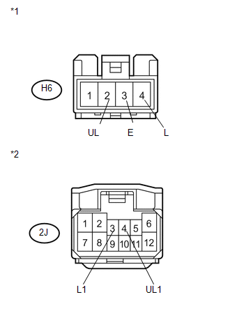
*1 |
Component without harness connected (Door Control Switch Assembly) |
|
*2 |
Unlock |
|
*3 |
Lock |
| NG | |
REPLACE DOOR CONTROL SWITCH ASSEMBLY |
|
|
3. |
CHECK HARNESS AND CONNECTOR (DOOR CONTROL SWITCH - MAIN BODY ECU AND BODY GROUND) |
|
(a) Disconnect the 2J driver side junction block connector. |
|
(b) Measure the resistance according to the value(s) in the table below.
Standard Resistance:
|
Tester Connection |
Condition |
Specified Condition |
|---|---|---|
|
H6-2 (UL) - 2J-4 (UL1) |
Always |
Below 1 Ω |
|
H6-4 (L) - 2J-3 (L1) |
Always |
Below 1 Ω |
|
H6-3 (E) - Body ground |
Always |
Below 1 Ω |
|
H6-2 (UL) - Body ground |
Always |
10 kΩ or higher |
|
H6-4 (L) - Body ground |
Always |
10 kΩ or higher |
|
*1 |
Front view of wire harness connector (to Door Control Switch Assembly) |
|
*2 |
Front view of wire harness connector (to Main Body ECU (Driver Side Junction Block Assembly)) |
| OK | |
REPLACE MAIN BODY ECU (DRIVER SIDE JUNCTION BLOCK ASSEMBLY) |
| NG | |
REPAIR OR REPLACE HARNESS OR CONNECTOR |
 Data List / Active Test
DATA LIST / ACTIVE TEST
1. DATA LIST
HINT:
Using the Techstream to read the Data List allows the values or states of switches,
sensors, actuators and other items to be read without removing any p ...
 Rear Door Lock
...
Other materials about Toyota Venza:
How To Proceed With Troubleshooting
CAUTION / NOTICE / HINT
HINT:
Use the following procedure listed to troubleshoot the Active Torque
Control 4WD system.
*: Use the Techstream.
PROCEDURE
1.
VEHICLE BROUGHT TO WORKSHOP
...
Taillight Relay Circuit
DESCRIPTION
The main body ECU (driver side junction block assembly) controls the operation
of the TAIL relay.
WIRING DIAGRAM
CAUTION / NOTICE / HINT
NOTICE:
Inspect the fuses for circuits related to this system before performing the following
inspec ...
Disassembly
DISASSEMBLY
PROCEDURE
1. REMOVE ENGINE COVER JOINT
(a) Remove the 3 joints.
2. REMOVE SPARK PLUG
3. REMOVE CAMSHAFT TIMING OIL CONTROL VALVE ASSEMBLY (for Intake Side)
4. REMOVE CAMSHAFT TIM ...

0.1351