Toyota Venza: Air Mix Damper Control Servo Motor Circuit (Driver Side) (B1446/46)
DESCRIPTION
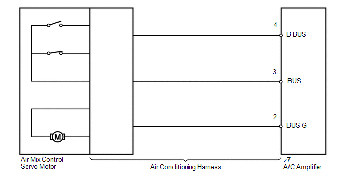
The air mix control servo motor sends pulse signals to indicate the damper position to the A/C amplifier. The A/C amplifier activates the motor (normal or reverse) based on these signals to move the air mix damper (driver side) to any position. As a result, the amount of air passing through the heater core after passing through the evaporator is adjusted, and the temperature of the air blowing toward the driver side is controlled.
The A/C amplifier communicates with the servo through a communication/driver IC and wiring assembly called the air conditioning harness.
HINT:
Confirm that no mechanical problem is present because this DTC can be output when either a damper link or the damper is mechanically locked.
|
DTC No. |
DTC Detection Condition |
Trouble Area |
|---|---|---|
|
B1446/46 |
Air mix damper position sensor value does not change even if A/C amplifier operates air mix control servo motor |
|
WIRING DIAGRAM
PROCEDURE
|
1. |
READ VALUE USING TECHSTREAM |
(a) Connect the Techstream to the DLC3.
(b) Turn the ignition switch to ON.
(c) Turn the Techstream on.
(d) Operate the driver side temperature adjustment switch.
(e) Enter the following menus: Body / Air Conditioner / Data List.
(f) Check the value(s) by referring to the table below.
Air Conditioner|
Tester Display |
Measurement Item/Range |
Normal Condition |
Diagnostic Note |
|---|---|---|---|
|
Air Mix Servo Targ Pulse (D) |
Driver side air mix servo motor target pulse / Min.: 0, Max.: 255 |
MAX. COLD: 5 (pulse) MAX. HOT: 103 (pulse) |
- |
OK:
The display is as specified in the Normal Condition column.
|
Result |
Proceed to |
|---|---|
|
NG |
A |
|
OK (When troubleshooting according to Problem Symptoms Table) |
B |
|
OK (When troubleshooting according to the DTC) |
C |
| B | .gif) |
PROCEED TO NEXT SUSPECTED AREA SHOWN IN PROBLEM SYMPTOMS TABLE |
| C | |
REPLACE A/C AMPLIFIER |
|
.gif)
|
2. |
PERFORM ACTIVE TEST USING TECHSTREAM |
(a) Connect the Techstream to the DLC3.
(b) Turn the ignition switch to ON.
(c) Turn the Techstream on.
(d) Enter the following menus: Body / Air Conditioner / Active Test.
(e) Check the operation by referring to the table below.
Air Conditioner|
Tester Display |
Test Part |
Control Range |
Diagnostic Note |
|---|---|---|---|
|
Air Mix Servo Targ Pulse (D) |
Air mix servo motor pulse (D side) |
Min.: 0, Max.: 255 |
- |
OK:
Air temperature changes in accordance with each control range.
| OK | |
REPLACE A/C AMPLIFIER |
|
|
3. |
INSPECT AIR MIX CONTROL SERVO MOTOR |
(a) Replace the No. 1 air mix control servo motor (air mix control servo motor)
(See page .gif) ).
).
HINT:
Since the servo motor cannot be inspected while it is removed from the vehicle, replace the servo motor with a new or a known good one and check that the condition returns to normal.
(b) Check for the DTC.
|
Result |
Proceed to |
|---|---|
|
DTC B1446/46 is output |
A |
|
DTC B1446/46 is not output |
B |
| B | |
REPLACE AIR MIX CONTROL SERVO MOTOR |
|
|
4. |
INSPECT AIR CONDITIONING HARNESS |
(a) Replace the air conditioning harness (See page
).
HINT:
Since the air conditioning harness cannot be inspected while it is removed from the vehicle, replace the air conditioning harness with a new or a known good one and check that the condition returns to normal.
(b) Check for the DTC.
|
Result |
Proceed to |
|---|---|
|
DTC B1446/46 is output |
A |
|
DTC B1446/46 is not output |
B |
| A | |
REPLACE A/C AMPLIFIER |
| B | |
REPLACE AIR CONDITIONING HARNESS |
 BUS IC Communication Malfunction (B1497/97)
DESCRIPTION
The air conditioning harness connects the A/C amplifier and each servo. The A/C
amplifier supplies power and sends operation instructions to each servo through
the air conditioning ha ...
 Air Inlet Damper Control Servo Motor Circuit (B1442/42)
DESCRIPTION
The air inlet control servo motor sends pulse signals to indicate the damper
position to the A/C amplifier. The A/C amplifier activates the motor (normal or
reverse) based on these si ...
Other materials about Toyota Venza:
System Description
SYSTEM DESCRIPTION
1. GENERAL
(a) Deceleration sensors used for the airbag system are installed on various
parts on the vehicle and calculate the deceleration rate of each part during a collision.
(b) Depending on the situation, the center airbag sensor a ...
Wireless Door Lock Tuner Circuit Malfunction (B1242)
DESCRIPTION
The door control receiver is used to receive electrical waves relating to the
entry functions of the smart key system. The certification ECU (smart key ECU assembly)
decodes the requested smart key system operation by identifying a key code ba ...
Installation
INSTALLATION
PROCEDURE
1. INSTALL REAR DOOR UPPER WINDOW FRAME MOULDING
(a) Engage the guide and install the rear door upper window frame moulding
to the door frame.
(b) Using an air riveter or ...

0.1284