Toyota Venza: Air Fuel Ratio Sensor
Components
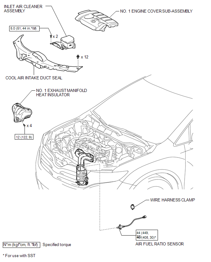
COMPONENTS
ILLUSTRATION
Removal
REMOVAL
PROCEDURE
1. REMOVE NO. 1 ENGINE COVER SUB-ASSEMBLY
.gif)
2. REMOVE COOL AIR INTAKE DUCT SEAL
3. REMOVE INLET AIR CLEANER ASSEMBLY
4. REMOVE NO. 1 EXHAUST MANIFOLD HEAT INSULATOR
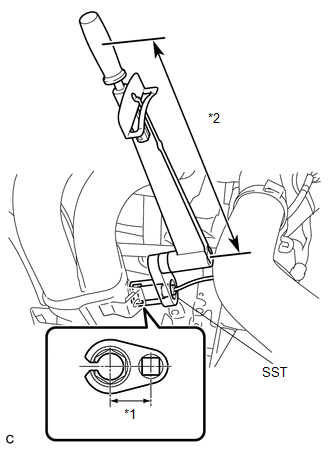
5. REMOVE AIR FUEL RATIO SENSOR
|
(a) Disconnect the air fuel ratio sensor connector. |
|
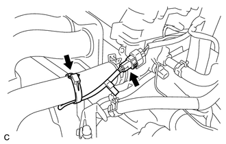
(b) Remove the wire harness clamp.
|
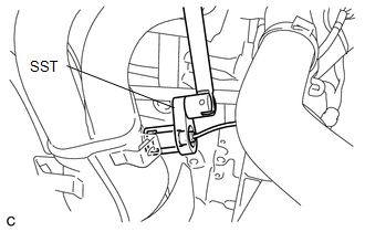
(c) Using SST, remove the air fuel ratio sensor from the exhaust manifold. SST: 09224-00011 |
|
Inspection
INSPECTION
PROCEDURE
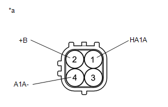
1. INSPECT AIR FUEL RATIO SENSOR (for Bank 1 Sensor 1)
|
(a) Measure the resistance according to the value(s) in the table below. Standard Resistance:
If the result is not as specified, replace the air fuel ratio sensor. Text in Illustration
|
|
Installation
INSTALLATION
PROCEDURE
1. INSTALL AIR FUEL RATIO SENSOR
|
(a) Using SST, install the air fuel ratio sensor to the exhaust manifold. Text in Illustration
SST: 09224-00011 Torque: without SST : 44 N·m {449 kgf·cm, 32 ft·lbf} with SST : 40 N·m {408 kgf·cm, 30 ft·lbf} NOTICE:
HINT: Perform "Inspection After Repair" after replacing the air fuel ratio
sensor (See page |
|
|
(b) Connect the air fuel ratio sensor connector. |
|
.png)
(c) Install the wire harness clamp.
2. INSPECT FOR EXHAUST GAS LEAK
3. INSTALL NO. 1 EXHAUST MANIFOLD HEAT INSULATOR
.gif)
4. INSTALL INLET AIR CLEANER ASSEMBLY
5. INSTALL COOL AIR INTAKE DUCT SEAL
6. INSTALL NO. 1 ENGINE COVER SUB-ASSEMBLY
 Accelerator Pedal
Components
COMPONENTS
ILLUSTRATION
On-vehicle Inspection
ON-VEHICLE INSPECTION
PROCEDURE
1. INSPECT ACCELERATOR PEDAL SENSOR ASSEMBLY
(a) Connect the Techstream to the DLC3.
(b) Turn the ...

Other materials about Toyota Venza:
Terminals Of Ecu
TERMINALS OF ECU
1. CHECK SLIDING ROOF ECU (SLIDING ROOF DRIVE GEAR SUB-ASSEMBLY)
(a) Disconnect the P4 ECU connector.
(b) Measure the resistance and voltage according to the value(s) in the table
below.
HINT:
Measure the values on the wire harness si ...
One or more Power Seat Motors do not Operate
DESCRIPTION
Signals are input into the position control ECU and switch assembly. The built-in
ECU manages the signals received from the position control ECU and switch assembly,
and operates each motor. If the position control ECU and switch assembly rece ...
Precaution
PRECAUTION
1. EXPRESSIONS OF IGNITION SWITCH
(a) The type of ignition switch used on this model differs according to the specifications
of the vehicle. The expressions listed in the table below are used in this section.
Switch Type
I ...

0.1395