Toyota Venza: Air Conditioning Control Panel Circuit
DESCRIPTION
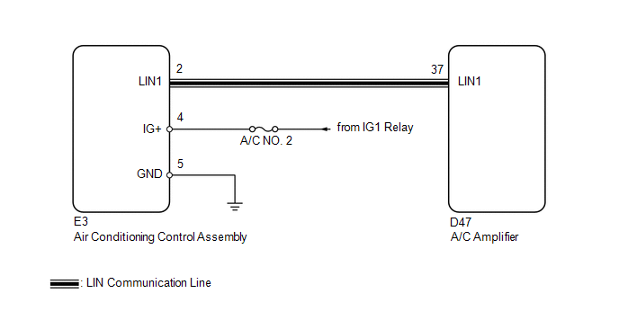
This circuit consists of the air conditioning control assembly and the A/C amplifier. When the air conditioning control assembly is operated, signals are transmitted to the A/C amplifier through the LIN communication system.
If the LIN communication system malfunctions, the A/C amplifier does not operate even if the air conditioning control assembly is operated.
WIRING DIAGRAM
CAUTION / NOTICE / HINT
NOTICE:
Inspect the fuses for circuits related to this system before performing the following inspection procedure.
PROCEDURE
|
1. |
CHECK HARNESS AND CONNECTOR (AIR CONDITIONING CONTROL ASSEMBLY - BODY GROUND) |
(a) Disconnect the air conditioning control assembly connector.
(b) Measure the resistance according to the value(s) in the table below.
Standard Resistance:
|
Tester Connection |
Condition |
Specified Condition |
|---|---|---|
|
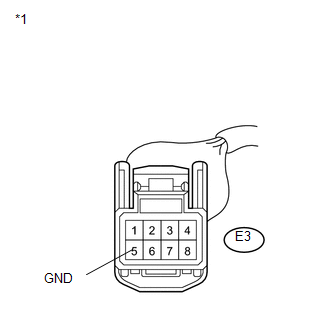
E3-5 (GND) - Body ground |
Always |
Below 1 Ω |
|
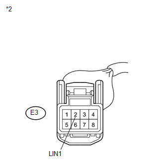
*1 |
Front view of wire harness connector (to Air Conditioning Control Assembly) |
| NG | .gif) |
REPAIR OR REPLACE HARNESS OR CONNECTOR |
|
.gif)
|
2. |
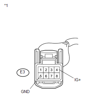
CHECK HARNESS AND CONNECTOR (AIR CONDITIONING CONTROL ASSEMBLY - BATTERY) |
|
(a) Measure the voltage according to the value(s) in the table below. Standard Voltage:
|
|
| NG | |
REPAIR OR REPLACE HARNESS OR CONNECTOR |
|
|
3. |
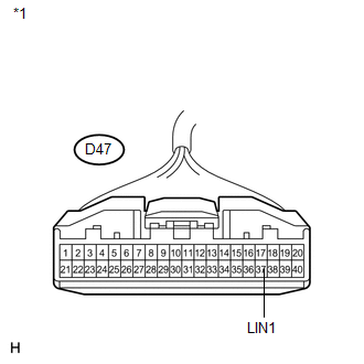
CHECK HARNESS AND CONNECTOR (A/C AMPLIFIER - AIR CONDITIONING CONTROL ASSEMBLY) |
|
(a) Disconnect the A/C amplifier connector. |
|
|
(b) Measure the resistance according to the value(s) in the table below. Standard Resistance:
|
|
| NG | |
REPAIR OR REPLACE HARNESS OR CONNECTOR |
|
|
4. |
INSPECT AIR CONDITIONING CONTROL ASSEMBLY |
(a) Replace the air conditioning control assembly (See page
.gif) ).
).
HINT:
Since the air conditioning control assembly cannot be inspected while it is removed from the vehicle, replace the air conditioning control assembly with a new or a known good one and check that the condition returns to normal.
(b) Operate the air conditioning control assembly to check that it functions properly.
|
Result |
Proceed to |
|---|---|
|
Air conditioning control assembly malfunctions |
A |
|
Air Conditioning control assembly functions properly |
B |
| A | |
PROCEED TO NEXT SUSPECTED AREA SHOWN IN PROBLEM SYMPTOMS TABLE |
| B | |
REPLACE AIR CONDITIONING CONTROL ASSEMBLY |
 Ambient Temperature Sensor Circuit (B1412/12)
DESCRIPTION
The ambient temperature sensor is installed in front of the condenser. It detects
the ambient temperature to control air conditioning AUTO mode. This sensor is connected
to the A/C am ...
 Air Conditioning Compressor Magnetic Clutch Circuit
DESCRIPTION
When the A/C amplifier is turned on, a magnetic clutch ON signal is sent from
the MGC terminal of the A/C amplifier. Then, the MGC relay turns on to operate the
magnetic clutch.
WIRI ...
Other materials about Toyota Venza:
USB Device Malfunction (B1585)
DESCRIPTION
This DTC is stored when a malfunction occurs in a connected device.
DTC No.
DTC Detection Condition
Trouble Area
B1585
When any of the following conditions is met:
A non m ...
Terminals Of Ecu
TERMINALS OF ECU
1. CHECK MAIN BODY ECU (DRIVER SIDE JUNCTION BLOCK ASSEMBLY)
(a) Disconnect the 2A and 2C main body ECU (driver side junction block) connectors.
(b) Disconnect the 2F main body ECU connector.
(c) Measure the voltage and resistance accord ...
Registration
REGISTRATION
PROCEDURE
1. DESCRIPTION OF CODE REGISTRATION
HINT:
The ID codes are the same as recognition codes for the wireless transmitter
and the engine immobiliser function. Registering an ID code enables the
smart key system, the wirel ...

0.1329