Toyota Venza: Adjustment
ADJUSTMENT
CAUTION / NOTICE / HINT
HINT:
- Use the same procedure for the RH side and LH side.
- The following procedure is for the LH side.
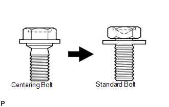
- Centering bolts are used to mount the door hinge to the vehicle body and door. The door cannot be adjusted with the centering bolts installed. Substitute the centering bolts with standard bolts (with washers) when making adjustments.
- Specified torque for standard bolts is shown in the standard bolt chart
(See page
.gif) ).
).
PROCEDURE
1. INSPECT BACK DOOR
(a) Check that the clearance measurements of areas *1 through *11 are within each standard range.
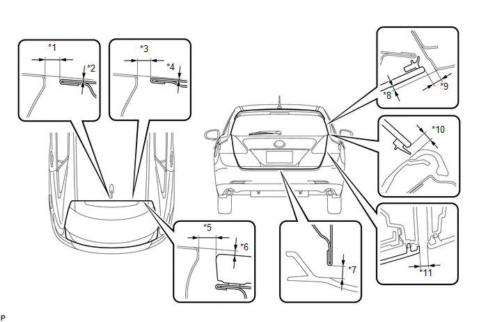 Standard Clearance
|
Area |
Measurement |
Area |
Measurement |
|---|---|---|---|
|
*1 |
6.3 to 9.3 mm (0.248 to 0.366 in.) |
*7 |
5.1 to 8.1 mm (0.201 to 0.319 in.) |
|
*2 |
0 to 3.0 mm (0 to 0.118 in.) |
*8 |
0.3 to 4.3 mm (0.0118 to 0.169 in.) |
|
*3 |
6.3 to 9.3 mm (0.248 to 0.366 in.) |
*9 |
4.0 to 7.0 mm (0.157 to 0.276 in.) |
|
*4 |
0.1 to 3.1 mm (0.00394 to 0.122 in.) |
*10 |
3.7 to 6.7 mm (0.146 to 0.264 in.) |
|
*5 |
6.6 to 9.6 mm (0.260 to 0.378 in.) |
*11 |
3.7 to 6.7 mm (0.146 to 0.264 in.) |
|
*6 |
0.1 to 3.1 mm (0.00394 to 0.122 in.) |
- |
- |
2. REMOVE REAR FLOOR FINISH PLATE
3. ADJUST BACK DOOR PANEL SUB-ASSEMBLY
|
(a) Before adjusting the upper end of the back door up and down or left and right, loosen the bolts. |
|
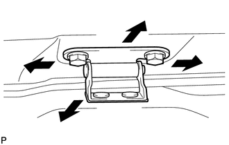
(b) Tighten the body side hinge after the adjustment.
Torque:
19 N·m {194 kgf·cm, 14 ft·lbf}
|
(c) Using a T40 "TORX" socket wrench, slightly loosen the striker mounting screws. |
|
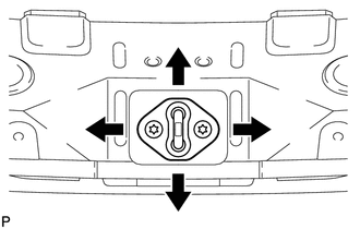
(d) Using a brass bar and a hammer, hit the striker to adjust its position.
(e) Using a T40 "TORX" socket wrench, tighten the striker mounting screws after the adjustment.
Torque:
23 N·m {235 kgf·cm, 17 ft·lbf}
4. INSTALL REAR FLOOR FINISH PLATE
 Components
COMPONENTS
ILLUSTRATION
ILLUSTRATION
ILLUSTRATION
ILLUSTRATION
ILLUSTRATION
...
 Disassembly
DISASSEMBLY
PROCEDURE
1. REMOVE UPPER BACK WINDOW PANEL TRIM
(a) Disengage the 4 clips and 4 claws, and remove the upper back window
panel trim.
...
Other materials about Toyota Venza:
Front Speed Sensor RH Circuit (C0200/31,C0205/32,C1271/71,C1272/72,C1330/35,C1331/36)
DESCRIPTION
The speed sensor detects wheel speed and sends the appropriate signals to the
skid control ECU. These signals are used for the ABS control system.
Speed sensor rotors have 48 serrations. The hall IC type speed sensor use the
frequency of outp ...
Luggage compartment light
1. Door position
2. Off
- Adjusting the rear personal/interior lights angle
Push the edge of the light lens.
- To prevent the battery from being discharged
►Vehicles with smart key system
If the personal/interior lights and “ENGIN ...
Installation
INSTALLATION
CAUTION / NOTICE / HINT
NOTICE:
When disconnecting the steering intermediate shaft assembly and pinion shaft
of steering gear assembly, be sure to place matchmarks before servicing.
PROCEDURE
1. INSTALL TIE ROD ASSEMBLY LH
(a) I ...

0.1151