Toyota Venza: Actuator Check
ACTUATOR CHECK
1. ACTUATOR CHECK
(a) Start the engine and warm it up.
(b) Perform the indicator check (See page .gif)
).
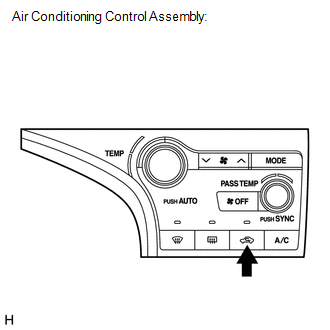
(c) Press the "Recirculation/Fresh" switch to perform the actuator check.
HINT:
Be sure to perform the actuator check after starting the engine.
Text in Illustration|
*1 |
Air Conditioning Control Assembly |
(d) As the actuator check is repeated from steps 1 to 10 at 1 second intervals, check the temperature and air flow visually and by hand.
.png)
HINT:
- The display blinks at 1 second intervals in the step operation.
- Press the "OFF" switch to finish panel diagnosis.
- Press the "AUTO" switch to enter sensor check mode.
|
*1 |
Accessory Meter Assembly (TFT) |
|
*2 |
Accessory Meter Assembly (LCD) |
|
*3 |
Display Code |
|
Step No. |
Display Code |
Condition |
||||
|---|---|---|---|---|---|---|
|
Blower Level |
Air Mix Damper |
Airflow Vent |
Air Inlet Damper |
Compressor |
||
|
1 |
0 |
0 |
0% open |
FACE |
FRESH |
off |
|
2 |
1 |
1 |
0% open |
FACE |
FRESH |
off |
|
3 |
2 |
17 |
0% open |
FACE |
RECIRCULATION/FRESH |
on |
|
4 |
3 |
17 |
0% open |
FACE |
RECIRCULATION |
on |
|
5 |
4 |
17 |
50% open |
B/L |
RECIRCULATION |
on |
|
6 |
5 |
17 |
50% open |
B/L |
RECIRCULATION |
on |
|
7 |
6 |
17 |
50% open |
FOOT |
FRESH |
on |
|
8 |
7 |
17 |
100% open |
FOOT-0 |
FRESH |
on |
|
9 |
8 |
17 |
100% open |
F/D |
FRESH |
on |
|
10 |
9 |
31 |
100% open |
DEF |
FRESH |
on |
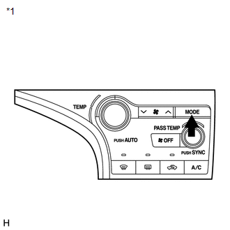
(e) If the steps are difficult to read because they change automatically, press the "MODE" switch to display the steps one at a time so that they can be read easily. The items are displayed step by step each time the "MODE" switch is pressed.
HINT:
- Press the "OFF" switch to finish panel diagnosis.
- Press the "Recirculation/Fresh" switch to enter sensor check mode.
|
*1 |
Air Conditioning Control Assembly |
 Diagnostic Trouble Code Chart
DIAGNOSTIC TROUBLE CODE CHART
HINT:
When the air conditioning system functions properly, DTC B1400/00 is output.
Air Conditioning System
DTC Code
Detection Item
Tr ...
 Lost Communication with ECM (U0100-U0142,U0155)
DESCRIPTION
DTC No.
DTC Detecting Condition
Trouble Area
U0100
No communication with ECM
CAN communication system
...
Other materials about Toyota Venza:
Removal
REMOVAL
PROCEDURE
1. REMOVE REAR SEAT HEADREST ASSEMBLY
2. REMOVE REAR SEAT CENTER HEADREST ASSEMBLY
3. REMOVE REAR SEAT INNER TRACK BRACKET COVER
4. REMOVE REAR SEAT OUTER TRACK BRACKET COVER
5. DISCONNECT REAR SEAT RECLINING CONTROL CABLE S ...
Removal
REMOVAL
CAUTION / NOTICE / HINT
NOTICE:
When disconnecting the steering intermediate shaft assembly and pinion shaft
of steering gear assembly, be sure to place matchmarks before servicing.
PROCEDURE
1. PLACE FRONT WHEELS FACING STRAIGHT AHEAD
2. SECUR ...
ECM Power Source Circuit
DESCRIPTION
When the ignition switch is turned to ON, the battery voltage is applied to IGSW
of the ECM. The output signal from the MREL terminal of the ECM causes a current
to flow to the coil, closing the contact of the engine room junction block assemb ...

0.1636