Toyota Venza: ABS Warning Light Remains ON
DESCRIPTION
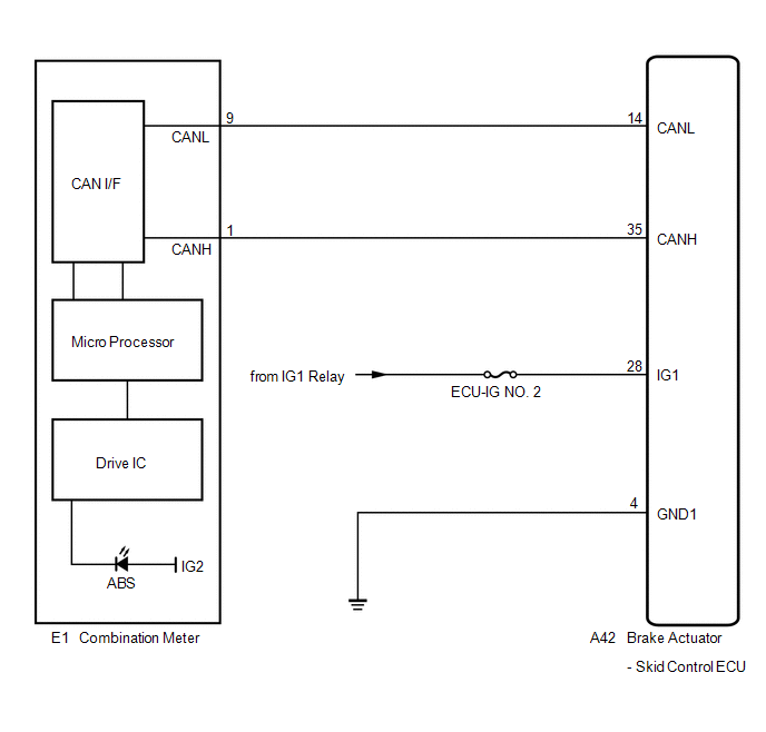
The skid control ECU is connected to the combination meter via CAN communication.
If any of the following is detected, the ABS warning light remains on:
- The skid control ECU connector is disconnected from the skid control ECU.
- There is a malfunction in the skid control ECU internal circuit.
- There is an open in the harness between the combination meter and the skid control ECU.
- The ABS control system is defective.
HINT:
In some cases, the Techstream cannot be used when the skid control ECU is abnormal.
WIRING DIAGRAM
PROCEDURE
|
1. |
CHECK CAN COMMUNICATION SYSTEM |
(a) Check if a CAN communication system DTC is output (See page
.gif) ).
).
|
Result |
Proceed to |
|---|---|
|
DTC is not output |
A |
|
DTC is output |
B |
| B | .gif) |
INSPECT CAN COMMUNICATION SYSTEM |
|
.gif)
|
2. |
CHECK IF SKID CONTROL ECU CONNECTOR IS SECURELY CONNECTED |
(a) Check if the skid control ECU connector is securely connected.
OK:
The connector is securely connected.
| NG | |
CONNECT CONNECTOR TO ECU CORRECTLY |
|
|
3. |
CHECK BATTERY |
(a) Check the battery voltage.
Standard Voltage:
11 to 14 V
|
Result |
Proceed to |
|---|---|
|
OK |
A |
|
NG (for 2GR-FE) |
B |
|
NG (for 1AR-FE) |
C |
| B | |
CHECK OR REPLACE CHARGING SYSTEM OR BATTERY (for 2GR-FE) |
| C | |
CHECK OR REPLACE CHARGING SYSTEM OR BATTERY (for 1AR-FE) |
|
|
4. |
INSPECT SKID CONTROL ECU (IG1 TERMINAL) |
|
(a) Disconnect the skid control ECU connector. |
|
.png)
(b) Turn the ignition switch to ON.
(c) Measure the voltage according to the value(s) in the table below.
Standard Voltage:
|
Tester Connection |
Switch Condition |
Specified Condition |
|---|---|---|
|
A42-28 (IG1) - Body ground |
Ignition switch ON |
11 to 14 V |
|
*1 |
Front view of wire harness connector (to Brake Actuator (Skid Control ECU)) |
| NG | |
REPAIR OR REPLACE HARNESS OR CONNECTOR (IG1 CIRCUIT) |
|
|
5. |
INSPECT SKID CONTROL ECU (GND1 TERMINAL) |
|
(a) Turn the ignition switch off. |
|
.png)
(b) Measure the resistance according to the value(s) in the table below.
Standard Resistance:
|
Tester Connection |
Condition |
Specified Condition |
|---|---|---|
|
A42-4 (GND1) - Body ground |
Always |
Below 1 ╬® |
|
*1 |
Front view of wire harness connector (to Brake Actuator (Skid Control ECU)) |
| NG | |
REPAIR OR REPLACE HARNESS OR CONNECTOR (GND1 CIRCUIT) |
|
|
6. |
INSPECT COMBINATION METER ASSEMBLY |
(a) Reconnect the skid control ECU connector.
(b) Perform the Active Test of the combination meter (meter CPU) using the Techstream
(See page ).
(c) Check the combination meter.
OK:
The ABS warning light turns on or off in accordance with the Techstream operation.
HINT:
If troubleshooting has been carried out according to Problem Symptoms Table,
refer back to the table and proceed to the next step before replacing the part (See
page ).
| OK | |
REPLACE BRAKE ACTUATOR ASSEMBLY |
| NG | |
REPLACE COMBINATION METER ASSEMBLY |
 Front Speed Sensor RH Circuit (C0200/31,C0205/32,C1271/71,C1272/72,C1330/35,C1331/36)
DESCRIPTION
The speed sensor detects wheel speed and sends the appropriate signals to the
skid control ECU. These signals are used for the ABS control system.
Speed sensor rotors have 48 serration ...
 ABS Warning Light does not Come ON
DESCRIPTION
The skid control ECU is connected to the combination meter via CAN communication.
WIRING DIAGRAM
Refer to ABS Warning Light Remains ON (See page
).
PROCEDURE
1.
...
Other materials about Toyota Venza:
Reassembly
REASSEMBLY
CAUTION / NOTICE / HINT
HINT:
Use an overhaul stand as necessary.
PROCEDURE
1. INSTALL DIFFERENTIAL RING GEAR
(a) Clean the contact surfaces of the rear differential case sub-assembly and
differential ring gear.
(b) Heat the differential ri ...
Installation
INSTALLATION
PROCEDURE
1. INSTALL THROTTLE BODY ASSEMBLY
(a) Install a new gasket to the intake manifold.
(b) Install the fuel tube bracket with the bolt.
Torque:
7.5 N┬Ęm {76 kgf┬ ...
Removal
REMOVAL
PROCEDURE
1. DISCONNECT CABLE FROM NEGATIVE BATTERY TERMINAL
NOTICE:
When disconnecting the cable, some systems need to be initialized after the cable
is reconnected (See page ).
2. REMOVE UPPER CONSOLE PANEL SUB-ASSEMBLY (w/o Seat Heater Syste ...

0.138