Toyota Venza: Starting System
Parts Location
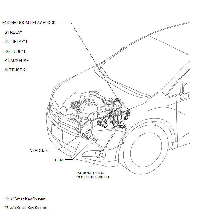
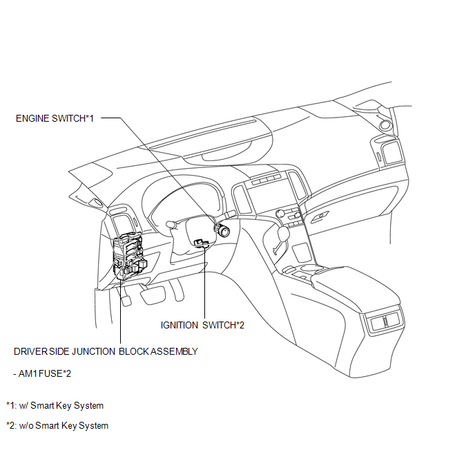
PARTS LOCATION
ILLUSTRATION
ILLUSTRATION
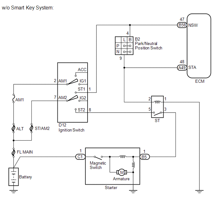
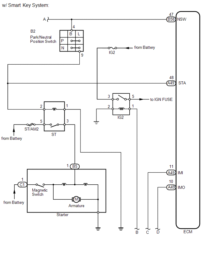
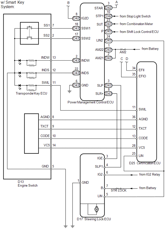
System Diagram
SYSTEM DIAGRAM
 Installation
INSTALLATION
PROCEDURE
1. INSTALL STARTER ASSEMBLY
(a) Install the starter with the 2 bolts.
Torque:
37 N·m {377 kgf·cm, 27 ft·lbf}
...
 Cruise Control
...
Other materials about Toyota Venza:
Crankshaft Position Sensor "A" Circuit (P0335,P0339)
DESCRIPTION
The crankshaft position sensor system consists of a crank angle sensor plate
and a pickup coil.
The sensor plate has 34 teeth and is installed on the crankshaft. The pickup
coil is made of wound copper wire, an iron core and magnet. The senso ...
Power Source Mode does not Change to ON (IG and ACC)
DESCRIPTION
When the engine switch is pushed with the electrical key in the cabin, the power
management control ECU receives signals to change the power source mode.
HINT:
To allow use of the Techstream to inspect the push-button start function when
the ...
Brake Switch "B" Circuit High (P0724)
DESCRIPTION
The purpose of this circuit is to prevent the engine from stalling when brakes
are suddenly applied while driving in lock-up condition.
When the brake pedal is depressed, the stop light switch sends a signal to the
ECM. Then the ECM cancels t ...

0.1139