Toyota Venza: Removal
REMOVAL
PROCEDURE
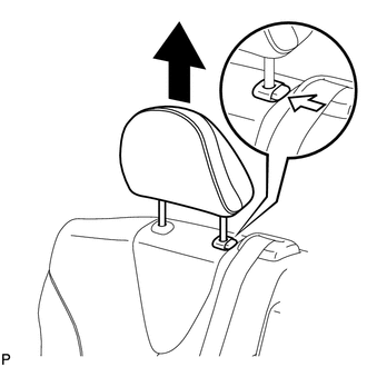
1. REMOVE REAR SEAT HEADREST ASSEMBLY
|
(a) Press the headrest support button and pull up the rear seat headrest assembly as shown in the illustration. |
|
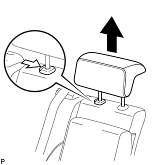
2. REMOVE REAR SEAT CENTER HEADREST ASSEMBLY
|
(a) Press the headrest support button and pull up the rear seat center headrest assembly as shown in the illustration. |
|
3. REMOVE REAR SEAT INNER TRACK BRACKET COVER
|
(a) Disengage the 3 claws and guide, and remove the rear seat inner track bracket cover as shown in the illustration. |
|
4. REMOVE REAR SEAT OUTER TRACK BRACKET COVER
|
(a) Disengage the 3 claws and guide, and remove the rear seat outer track bracket cover as shown in the illustration. |
|
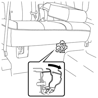
5. DISCONNECT REAR SEAT RECLINING CONTROL CABLE SUB-ASSEMBLY
(a) Pull down the adjuster's lock piece to release the lock as shown in the illustration.
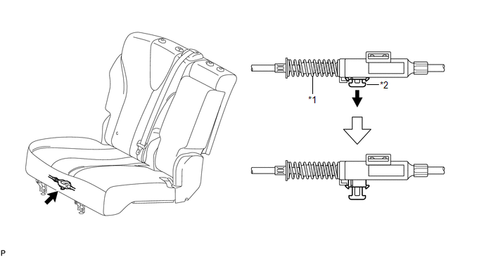 Text in Illustration
|
*1 |
Adjuster Spring |
*2 |
Lock Piece |
|
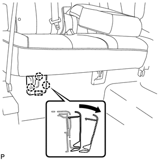
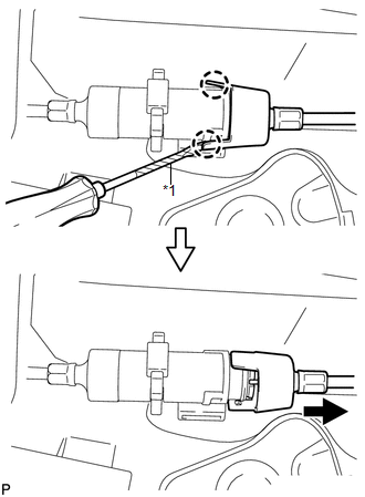
(b) Using a screwdriver wrapped with protective tape, disengage the 2 claws as shown in the illustration. Text in Illustration
|
|
(c) Lift up the seat track adjusting handle to the uppermost position and hold the handle in this position as shown in the illustration.
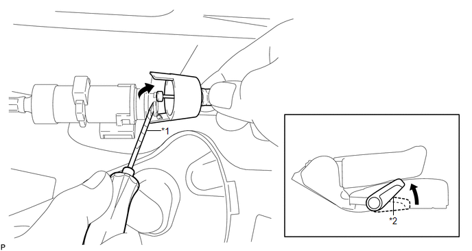 Text in Illustration
|
*1 |
Protective Tape |
*2 |
Seat Track Adjusting Handle |
(d) Using a screwdriver wrapped with protective tape, disconnect the rear seat reclining control cable sub-assembly as shown in the illustration.
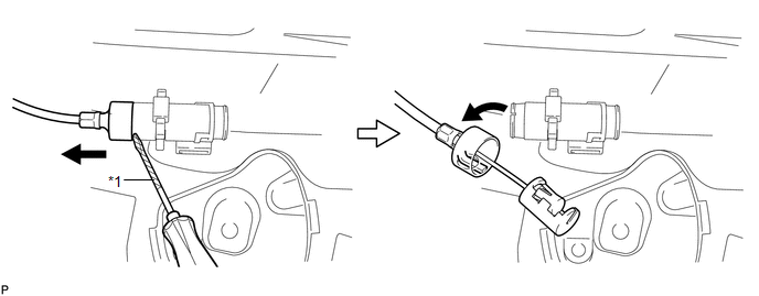 Text in Illustration
|
*1 |
Protective Tape |
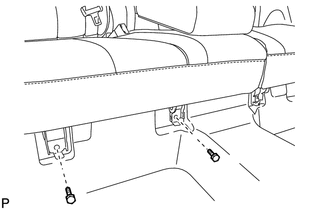
6. REMOVE REAR SEAT ASSEMBLY RH
|
(a) Remove the 3 bolts on the rear side of the seat. |
|
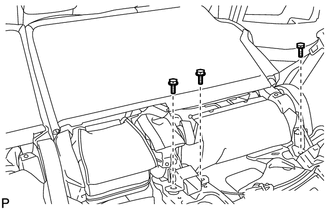
|
(b) Remove the 2 bolts on the front side of the rear seat assembly RH. |
|
(c) Remove the rear seat assembly RH.
NOTICE:
Be careful not to damage the vehicle body.
 Components
COMPONENTS
ILLUSTRATION
ILLUSTRATION
ILLUSTRATION
ILLUSTRATION
ILLUSTRATION
...
 Disassembly
DISASSEMBLY
PROCEDURE
1. REMOVE SEAT ADJUSTER COVER CAP RH
(a) Using a screwdriver wrapped with protective tape, disengage the 3
claws and remove the seat adjuster cover cap RH.
T ...
Other materials about Toyota Venza:
Disassembly
DISASSEMBLY
PROCEDURE
1. REMOVE TRANSFER AND TRANSAXLE SETTING STUD BOLT
(a) Remove the 4 transfer and transaxle setting stud bolts.
2. REMOVE NO. 2 TRANSFER CASE PLUG
(a) Remove the No. ...
Malfunction in Deceleration Sensor (C1245/93)
DESCRIPTION
If a malfunction in the deceleration sensor circuit occurs, the AWD control ECU
will output this DTC.
DTC No.
DTC Detecting Condition
Trouble Area
C1296/96
When the following conditio ...
Chassis
General Maintenance
GENERAL MAINTENANCE
PROCEDURE
1. INSPECT STEERING LINKAGE AND GEAR HOUSING
(a) Check the steering wheel free play (See page
).
(b) Check the steering linkage for looseness or damage.
(1) Check that the tie rod ends do not have any ...

0.1352