Toyota Venza: Removal
REMOVAL
PROCEDURE
1. REMOVE REAR WHEELS
2. SEPARATE REAR STABILIZER LINK ASSEMBLY LH
|
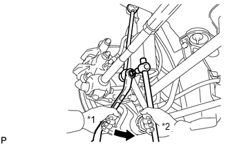
(a) Remove the nut and separate the rear stabilizer link assembly LH from the rear stabilizer bar. Text in Illustration
HINT: If the ball joint turns together with the nut, use a hexagon wrench (5 mm) to hold the stud bolt. |
|
3. SEPARATE REAR STABILIZER LINK ASSEMBLY RH
HINT:
Perform the same procedure as the LH side.
4. REMOVE REAR STABILIZER BAR
.gif)
5. SEPARATE REAR HEIGHT CONTROL SENSOR SUB-ASSEMBLY (w/ HID Headlight System)
|
(a) Remove the nut and separate the rear height control sensor sub-assembly from the rear No. 2 suspension arm assembly RH. NOTICE: Use wire or an equivalent tool to keep the rear height control sensor link from hanging down. |
|
.png)
6. REMOVE REAR NO. 2 SUSPENSION ARM ASSEMBLY LH
|
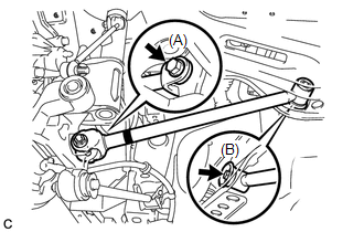
(a) Remove the bolt (A) and the nut, and separate the rear No. 2 suspension arm assembly LH from the rear axle carrier sub-assembly LH. NOTICE: Since a stopper nut is used, loosen the bolt. |
|
.png)
(b) Remove the bolt (B) and the rear No. 2 suspension arm assembly LH.
7. REMOVE REAR NO. 2 SUSPENSION ARM ASSEMBLY RH
HINT:
Perform the same procedure as the LH side.
8. REMOVE REAR NO. 1 SUSPENSION ARM ASSEMBLY LH
|
(a) Remove the bolt and the nut, and separate the rear No. 1 suspension arm assembly LH from the rear axle carrier sub-assembly. NOTICE: Since a stopper nut is used, loosen the bolt. |
|
(b) Remove the bolt and the rear No. 1 suspension arm assembly LH.
9. REMOVE REAR NO. 1 SUSPENSION ARM ASSEMBLY RH
HINT:
Perform the same procedure as the LH side.
 Installation
INSTALLATION
PROCEDURE
1. TEMPORARILY INSTALL REAR NO. 1 SUSPENSION ARM ASSEMBLY LH
(a) Temporarily install the rear No. 1 suspension arm assembly LH to
the rear suspension member wi ...

Other materials about Toyota Venza:
Air conditioning filter
The air conditioning filter must be changed regularly to maintain air conditioning
efficiency.
- Removal method
Vehicles with smart key system:
Turn the “ENGINE START STOP” switch off.
Vehicles without smart key system:
Turn the engine switch ...
Customize Parameters
CUSTOMIZE PARAMETERS
NOTICE:
When the customer requests a change in a function, first make sure that
the function can be customized.
Be sure to make a note of the current settings before customizing.
When troubleshooting a function, fi ...
Installation
INSTALLATION
PROCEDURE
1. INSTALL STUD BOLT (for LH Side)
(a) Install the stud bolt.
Torque:
17 N·m {173 kgf·cm, 13 ft·lbf}
2. INSTALL STUD BOLT (for RH Side)
HINT:
Perform the same proc ...

0.1882