Toyota Venza: Power Source Mode does not Change to ON (ACC)
DESCRIPTION
When the engine switch is pushed with the electrical key in the cabin, the power management control ECU receives signals to change the power source mode.
HINT:
To allow use of the Techstream to inspect the push-button start function when the power source mode is off, repeat opening and closing any of the doors. Opening and closing a door establishes communication between the Techstream and the power management control ECU. (Opening and closing a door can also be simulated by operating a door courtesy light switch.)
WIRING DIAGRAM
Refer to DTC B2274 (See page .gif) ).
).
PROCEDURE
|
1. |
CHECK HARNESS AND CONNECTOR (BATTERY - POWER MANAGEMENT CONTROL ECU) |
See page
| NG | .gif) |
REPAIR OR REPLACE HARNESS OR CONNECTOR (BATTERY - POWER MANAGEMENT CONTROL ECU) |
|
.gif)
|
2. |
CHECK HARNESS AND CONNECTOR |
See page
| NG | |
REPAIR OR REPLACE HARNESS OR CONNECTOR |
|
|
3. |
INSPECT ACC RELAY |
See page
| NG | |
REPLACE ACC RELAY |
|
|
4. |
CHECK HARNESS AND CONNECTOR |
See page
| NG | |
REPAIR OR REPLACE HARNESS OR CONNECTOR |
|
|
5. |
CHECK HARNESS AND CONNECTOR |
See page
| NG | |
REPAIR OR REPLACE HARNESS OR CONNECTOR |
|
|
6. |
CHECK POWER MANAGEMENT CONTROL ECU |
|
(a) Reconnect the all connectors. |
|
(b) Measure the voltage according to the value(s) in the table below.
Standard Voltage:
|
Tester Connection |
Condition |
Specified Condition |
|---|---|---|
|
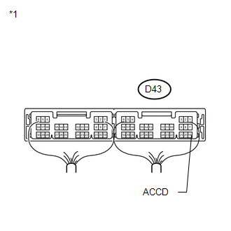
D43-19 (ACCD) - Body ground |
Engine switch off |
Below 1 V |
|
D43-19 (ACCD) - Body ground |
Engine switch on (IG) |
Output voltage at terminal AM21 or AM22 -2 V or more |
|
*1 |
Components with harness connected (Power Management Control ECU) |
| OK | |
REPLACE MAIN BODY ECU (DRIVER SIDE JUNCTION BLOCK ASSEMBLY) |
| NG | |
REPLACE POWER MANAGEMENT CONTROL ECU |
 Power Source Mode does not Change to ON (IG)
DESCRIPTION
When the engine switch is pushed with the electrical key in the cabin, the power
management control ECU receives signals to change the power source mode.
HINT:
To allow use of the Tec ...

Other materials about Toyota Venza:
Pcv Valve
Components
COMPONENTS
ILLUSTRATION
Removal
REMOVAL
PROCEDURE
1. REMOVE INTAKE MANIFOLD
(a) Remove the intake manifold (See page ).
2. REMOVE VENTILATION VALVE SUB-ASSEMBLY
(a) Disconnect the No. 2 ventilation hose from the ventilatio ...
Inspection
INSPECTION
PROCEDURE
1. INSPECT INNER REAR VIEW MIRROR ASSEMBLY
(a) Inspect operation of the electrochromic inner mirror.
(1) Connect a positive (+) lead from the battery to terminal 1 and a negative
(-) lead to terminal 2.
(2) Press the AUTO switch.
...
Inspection
INSPECTION
PROCEDURE
1. INSPECT ENGINE SWITCH
(a) Measure the resistance according to the value(s) in the table below.
Standard Resistance:
Tester Connection
Switch Condition
Specified Condition
7 (SS1) ...

0.1748