Toyota Venza: Parts Location
PARTS LOCATION
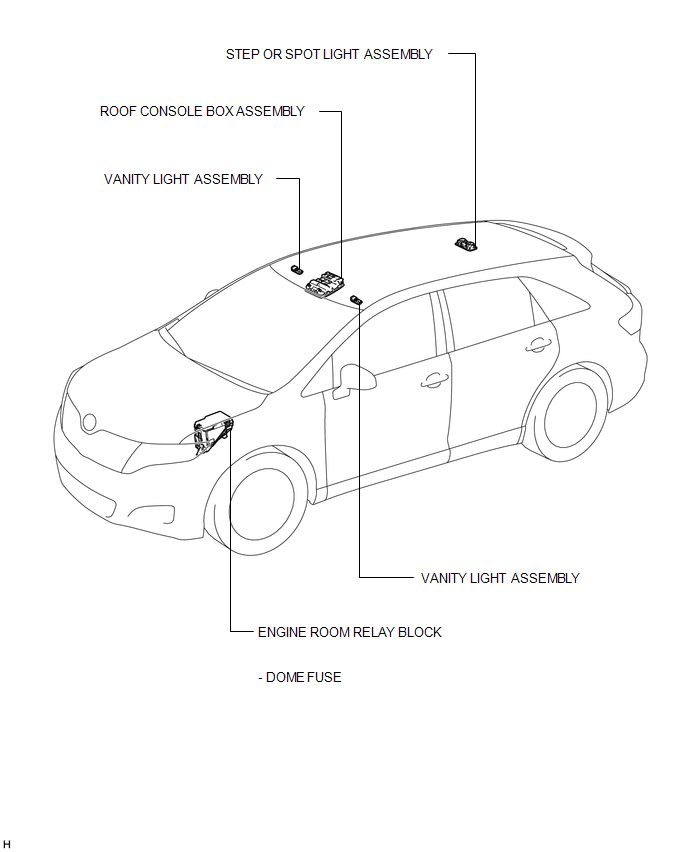
ILLUSTRATION
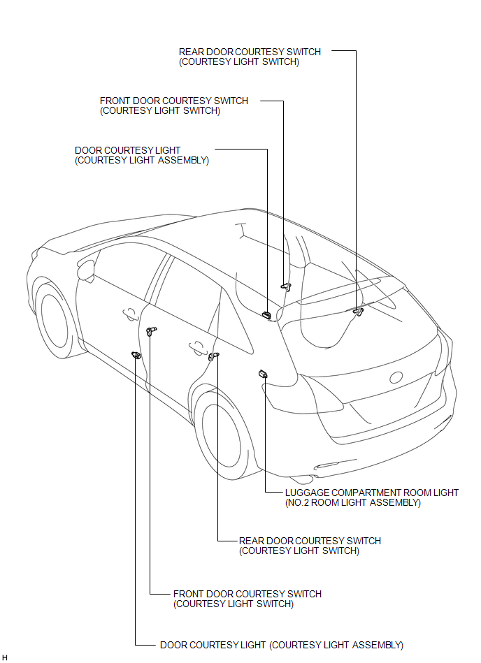
ILLUSTRATION
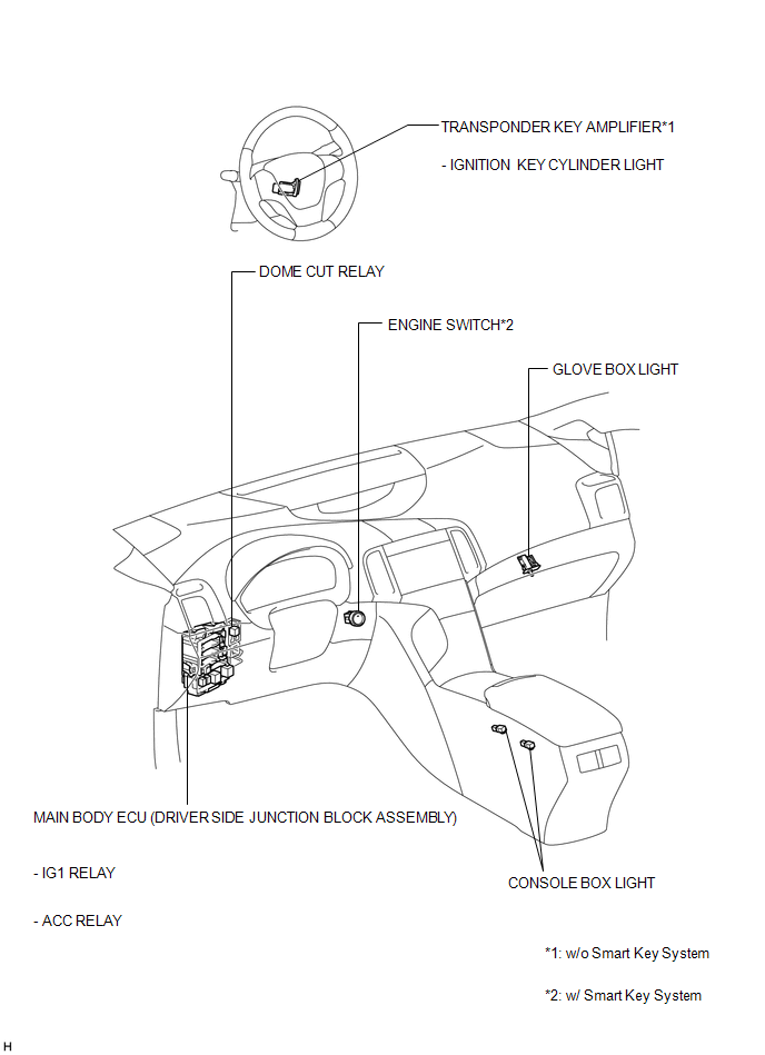
ILLUSTRATION
ILLUSTRATION
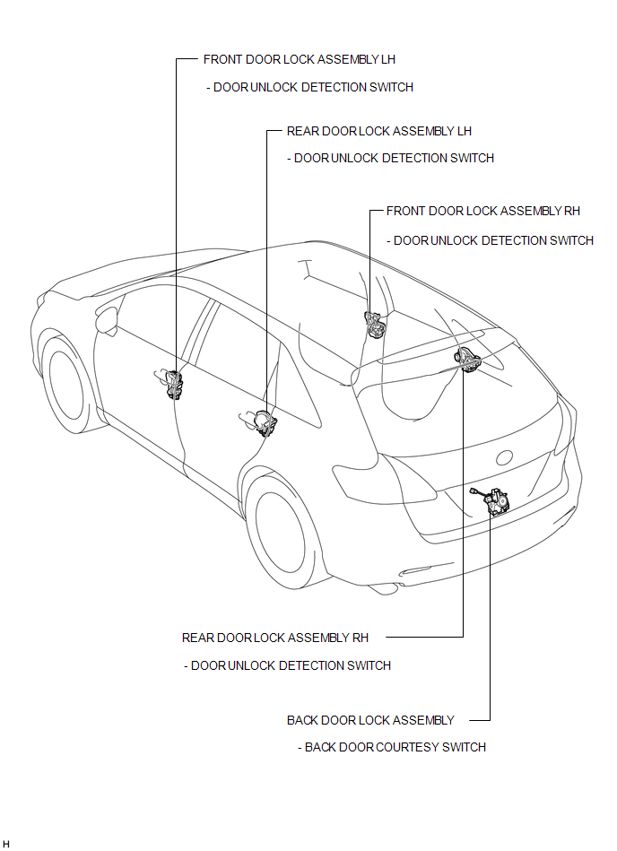
 Lighting System
...
 Precaution
PRECAUTION
NOTICE:
When disconnecting the cable from the negative (-) battery terminal, initialize
the following systems after the cable is reconnected.
System Name
See Proc ...
Other materials about Toyota Venza:
Replacement
REPLACEMENT
CAUTION / NOTICE / HINT
CAUTION:
Prolonged and repeated contact with engine oil will result in the removal
of natural oils from the skin, leading to dryness, irritation and dermatitis.
In addition, used engine oil contains potent ...
Clearance Warning Buzzer Circuit
DESCRIPTION
This circuit consists of the No. 1 clearance warning buzzer and clearance warning
ECU assembly. An ECU-excited type buzzer is used. The ECU operates the buzzer using
a sound pattern that changes depending on the distance to the obstacle.
WIRI ...
Weight limits
• The gross trailer weight must never exceed TWR described in the table. • The
gross combination weight must never exceed the GCWR described in the table.
• The gross vehicle weight must never exceed the GVWR indicated on the Certification
Label. ...

0.1396