Toyota Venza: Parts Location
PARTS LOCATION
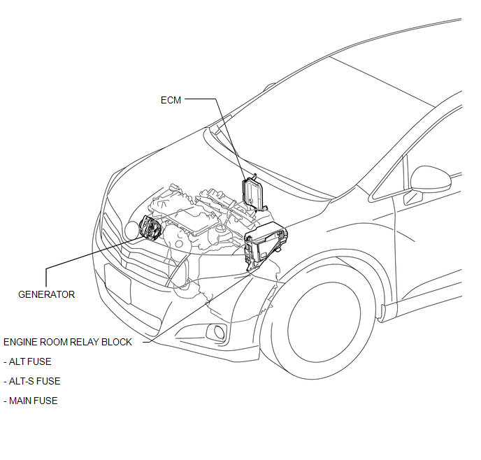
ILLUSTRATION
ILLUSTRATION
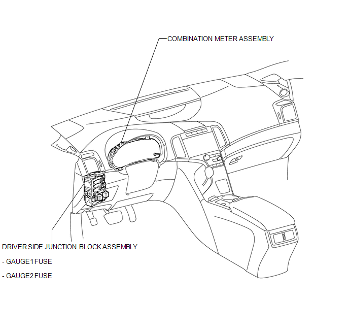
 Charging System
...
 Precaution
PRECAUTION
1. Check that the battery cables are connected to the correct terminals.
2. Disconnect the battery cables when the battery is given a quick charge.
3. Do not perform tests with a high vo ...
Other materials about Toyota Venza:
System Description
SYSTEM DESCRIPTION
1. GENERAL
The rear window defogger wires are attached to the inside of the rear window
and defog the window surface quickly by pressing the rear window defogger switch
on the air conditioning control assembly. The indicator light is i ...
System Diagram
SYSTEM DIAGRAM
Communication Table
Transmitting ECU (Transmitter)
Receiving ECU (Receiver)
Signal
Line
Certification ECU
(Smart key ECU assembly)
Main body ECU
(Driver side junc ...
Front Occupant Classification Sensor RH Collision Detection (B1786)
DESCRIPTION
DTC B1786 is output when the occupant classification ECU receives a collision
detection signal sent by the front occupant classification sensor RH if an accident
occurs.
DTC B1786 is also output when the front seat assembly RH is subjected to ...

0.1615