Toyota Venza: On-vehicle Inspection
ON-VEHICLE INSPECTION
CAUTION / NOTICE / HINT
HINT:
- Use the same procedure for the RH side and LH side.
- The procedure listed below is for the LH side.
PROCEDURE
1. REMOVE FRONT WHEEL
2. SEPARATE FRONT DISC BRAKE CALIPER ASSEMBLY
.gif)
3. REMOVE FRONT DISC
4. INSPECT FRONT AXLE HUB BEARING LOOSENESS
|
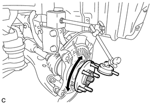
(a) Using a dial indicator, check for looseness near the center of the front axle hub. Maximum looseness: 0.05 mm (0.00196 in.) NOTICE: Ensure that the dial indicator is set perpendicular to the measurement surface. If the looseness exceeds the maximum, replace the front axle hub bearing. |
|

5. INSPECT FRONT AXLE HUB RUNOUT
|
(a) Using a dial indicator, check for runout on the surface of the axle hub outside the hub bolt. Maximum runout: 0.05 mm (0.00196 in.) NOTICE: Ensure that the dial indicator is set perpendicular to the measurement surface. If the runout exceeds the maximum, replace the front axle hub sub-assembly. |
|
6. INSTALL FRONT DISC
7. INSTALL FRONT DISC BRAKE CALIPER ASSEMBLY
8. INSTALL FRONT WHEEL
Torque:
103 N·m {1050 kgf·cm, 76 ft·lbf}
 Components
COMPONENTS
ILLUSTRATION
ILLUSTRATION
...
 Removal
REMOVAL
CAUTION / NOTICE / HINT
HINT:
Use the same procedure for the RH side and LH side.
The procedure listed below is for the LH side.
PROCEDURE
1. REMOVE FRONT WHEEL
2. REMO ...
Other materials about Toyota Venza:
Driver Side Seat Belt Warning Light does not Operate
DESCRIPTION
When the ignition switch is ON, the center airbag sensor assembly transmits front
seat inner belt status signals to the combination meter assembly through CAN. If
the driver seat belt is not fastened, the combination meter assembly blinks the ...
Back Door Closer Operation Malfunction (B2250)
DESCRIPTION
The power back door ECU (power back door motor unit)*1 or back door closer ECU
(multiplex network door ECU)*2 receives signals from the latch switch, sector switch
and back door courtesy switch, which are built into the back door lock. Based o ...
Rear Occupant Classification Sensor LH Collision Detection (B1787)
DESCRIPTION
DTC B1787 is output when the occupant classification ECU receives a collision
detection signal sent by the rear occupant classification sensor LH if an accident
occurs.
DTC B1787 is also output when the front seat assembly RH is subjected to ...

0.1328