Toyota Venza: Installation
INSTALLATION
PROCEDURE
1. INSTALL WINDSHIELD WIPER SWITCH ASSEMBLY
|
(a) Engage the claw to install the windshield wiper switch assembly as shown in the illustration. |
|
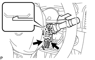
(b) Connect the 2 connectors.
2. INSTALL UPPER STEERING COLUMN COVER
|
(a) Engage the 3 claws and 4 clips to install the upper steering column cover to the lower instrument cover. |
|
.png)
3. INSTALL LOWER STEERING COLUMN COVER
|
(a) Engage the 3 claws to install the lower steering column cover to the upper steering column cover. |
|
.png)
|
(b) Turn the steering wheel assembly to the left and install the screw shown in the illustration. |
|
.png)
|
(c) Turn the steering wheel assembly to the right and install the screw shown in the illustration. |
|
.png)
4. INSTALL LOWER NO. 1 INSTRUMENT PANEL FINISH PANEL
.gif)
5. INSTALL COWL SIDE TRIM SUB-ASSEMBLY LH
6. INSTALL FRONT DOOR SCUFF PLATE LH
 Inspection
INSPECTION
PROCEDURE
1. INSPECT WINDSHIELD WIPER SWITCH ASSEMBLY
(a) Measure the resistance according to the value(s) in the table below.
Standard Resistance:
Front Wiper Switch
...
 Door Lock
...
Other materials about Toyota Venza:
Problem Symptoms Table
PROBLEM SYMPTOMS TABLE
HINT:
Use the table below to help determine the cause of problem symptoms.
If multiple suspected areas are listed, the potential causes of the symptoms
are listed in order of probability in the "Suspected Area" ...
Speedometer Malfunction
DESCRIPTION
The meter CPU receives vehicle speed signals from the skid control ECU via the
CAN communication system (CAN No. 1 Bus). The speed sensor detects the wheel speed
and sends the appropriate signals to the skid control ECU. The skid control ECU
...
Removal
REMOVAL
PROCEDURE
1. REMOVE BRAKE BOOSTER ASSEMBLY
HINT:
Refer to the instructions for Removal of the brake booster assembly (See page
).
2. REMOVE HEADLIGHT LEVELING ECU ASSEMBLY (w/ HID Headlight System)
3. REMOVE STOP LIGHT SWITCH ASSEMBLY
4. ...

0.1197