Toyota Venza: Installation
INSTALLATION
PROCEDURE
1. INSTALL HOOD LOCK CONTROL CABLE ASSEMBLY
(a) Pass the hood lock control cable assembly into the engine compartment.
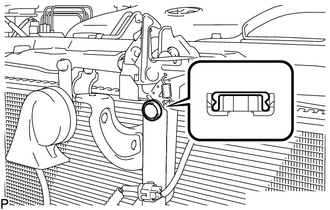
(b) Pass the cable through the upper radiator support.
(c) Engage the each clamp shown in the illustration.
2. INSTALL LOWER NO. 1 INSTRUMENT PANEL FINISH PANEL
.gif)
3. INSTALL COWL SIDE TRIM SUB-ASSEMBLY LH
4. INSTALL FRONT DOOR SCUFF PLATE LH
5. INSTALL HOOD LOCK ASSEMBLY (w/o Engine Hood Courtesy Switch)
|
(a) Apply MP grease to the sliding areas of the lock. |
|
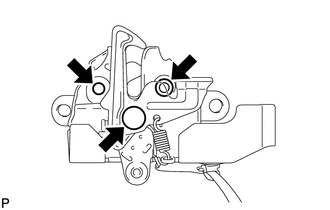
(b) Connect the hood lock control cable.
|
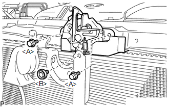
(c) Install the hood lock assembly with the 3 bolts. Torque: <A> Centering Bolt : 8.0 N·m {82 kgf·cm, 71 in·lbf} Torque: <A> Standard Bolt : 7.5 N·m {77 kgf·cm, 66 in·lbf} Torque: <B> : 8.0 N·m {82 kgf·cm, 71 in·lbf} |
|
|
(d) Install a new hood lock nut cap. |
|
6. INSTALL HOOD LOCK ASSEMBLY (w/ Engine Hood Courtesy Switch)
|
(a) Apply MP grease to the sliding areas of the lock. |
|
(b) Connect the hood lock control cable.
|
(c) Install the hood lock assembly with the 3 bolts. Torque: <A> Centering Bolt : 8.0 N·m {82 kgf·cm, 71 in·lbf} Torque: <A> Standard Bolt : 7.5 N·m {77 kgf·cm, 66 in·lbf} Torque: <B> : 8.0 N·m {82 kgf·cm, 71 in·lbf} |
|
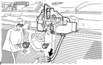
(d) Connect the connector.
|
(e) Install a new hood lock nut cap. |
|
7. INSTALL LOW PITCHED HORN ASSEMBLY
8. INSTALL RADIATOR GRILLE
9. INSTALL COOL AIR INTAKE DUCT SEAL
10. INSTALL FRONT FENDER LINER LH
(a) Install the front fender liner LH with new grommet.
(b) Install the 5 clips <A>.
(c) Install the clip <B>.
(d) Install the bolt and 6 clips.
|
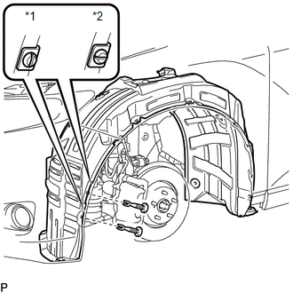
(e) Install the 2 pin hold clips. Text in Illustration
NOTICE: Insert the pin hold clip with the slot aligned vertically. Do not rotate the clip after inserting it. After installation, confirm that the slot is vertical. |
|
11. INSTALL FRONT WHEEL LH
12. INSTALL FRONT FENDER OUTSIDE MOULDING LH
13. INSPECT HOOD SUB-ASSEMBLY
14. ADJUST HOOD SUB-ASSEMBLY
 Components
COMPONENTS
ILLUSTRATION
ILLUSTRATION
...
 Removal
REMOVAL
PROCEDURE
1. REMOVE FRONT WHEEL LH
2. REMOVE FRONT FENDER OUTSIDE MOULDING LH
3. REMOVE FRONT FENDER LINER LH
(a) Using a screwdriver, turn the pin 90 degrees and remove the ...
Other materials about Toyota Venza:
Front Axle Hub Bolt
Components
COMPONENTS
ILLUSTRATION
Replacement
REPLACEMENT
CAUTION / NOTICE / HINT
HINT:
Use the same procedure for the RH side and LH side.
The procedure listed below is for the LH side.
PROCEDURE
1. REMOVE FRONT WHEEL
2. SEP ...
CD cannot be Ejected
PROCEDURE
1.
CHECK OPERATION
(a) Press the disc eject switch of the radio and display receiver assembly for
5 seconds or more and check that the CD is ejected.
OK:
CD is ejected.
NG
REPLACE RADIO AND D ...
Components
COMPONENTS
ILLUSTRATION
ILLUSTRATION
ILLUSTRATION
ILLUSTRATION
ILLUSTRATION
...

0.1206