Toyota Venza: Headlight Signal Circuit
DESCRIPTION
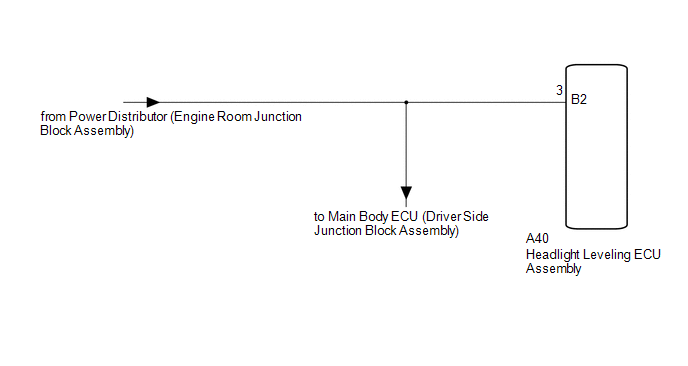
The headlight leveling ECU assembly detects the low beam headlights status.
WIRING DIAGRAM
CAUTION / NOTICE / HINT
NOTICE:
First check that the low beam headlights operate normally.
PROCEDURE
|
1. |
CHECK HARNESS AND CONNECTOR (ENGINE ROOM JUNCTION BLOCK ASSEMBLY - ECU) |
|
(a) Disconnect the A40 headlight leveling ECU assembly connector. |
|
(b) Measure the voltage according to the value(s) in the table below.
Standard Voltage:
|
Tester Connection |
Switch Condition |
Specified Condition |
|---|---|---|
|
A40-3 (B2) - Body ground |
Light control switch in head position |
11 to 14 V |
|
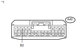
*1 |
Front view of wire harness connector (to Headlight Leveling ECU assembly) |
| OK | .gif) |
PROCEED TO NEXT SUSPECTED AREA SHOWN IN PROBLEM SYMPTOMS TABLE |
| NG | |
REPAIR OR REPLACE HARNESS OR CONNECTOR |
 Front Fog Light Circuit
DESCRIPTION
The main body ECU (driver side junction block assembly) controls the fog light
relay.
WIRING DIAGRAM
CAUTION / NOTICE / HINT
NOTICE:
Inspect the fuses for circuits related to this ...
 Light Control Switch Circuit
DESCRIPTION
The main body ECU (driver side junction block assembly) receives the following
switch information:
Light control switch position off, tail, head or AUTO
Dimmer switch positi ...
Other materials about Toyota Venza:
How To Proceed With Troubleshooting
CAUTION / NOTICE / HINT
HINT:
Use the following procedure to troubleshoot the rear view monitor system.
*: Use the Techstream.
PROCEDURE
1.
VEHICLE BROUGHT TO WORKSHOP
NEXT
...
Horn Circuit
DESCRIPTION
When the theft deterrent system is switched from the armed state to the alarm
sounding state, the main body ECU (driver side junction block assembly) transmits
a signal to cause the horn to sound at intervals of 0.4 seconds.
WIRING DIAGRAM
...
Installation
INSTALLATION
PROCEDURE
1. INSTALL SPIRAL WITH SENSOR CABLE SUB-ASSEMBLY
(a) Install the spiral with sensor cable sub-assembly (See page
).
NOTICE:
Do not replace the spiral cable with the battery connected and the engine
switch on (IG).
...

0.1379