
Toyota Venza: Components
COMPONENTS
ILLUSTRATION
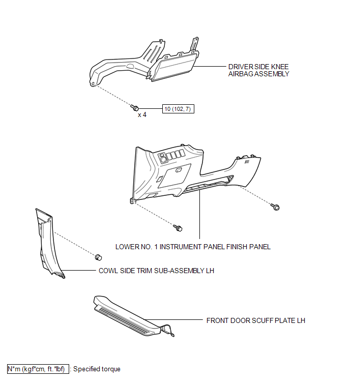

 On-vehicle Inspection
ON-VEHICLE INSPECTION
CAUTION / NOTICE / HINT
CAUTION:
Be sure to follow the correct removal and installation procedures of the driver
side knee airbag assembly.
PROCEDURE
1. INSPECT DRIVER SID ...
Other materials about Toyota Venza:
Headlight switch
The headlights can be operated manually or automatically.
Turning the end of the lever turns on the lights as follows.
Type A
The daytime running lights turn
on.
The headlights, parking lights, daytime running lights and so on turn on and
off auto ...
Inspection
INSPECTION
PROCEDURE
1. INSPECT SPIRAL CABLE
(a) Visually check for defects with the spiral cable removed from the vehicle.
(1) The defects are as follows:
Scratches on the spiral cable
Small cracks the spiral cable
Dents on the spiral cabl ...
Removal
REMOVAL
CAUTION / NOTICE / HINT
HINT:
Perform "Inspection After Repair" after replacing the fuel injector assembly
(See page ).
PROCEDURE
1. DISCHARGE FUEL SYSTEM PRESSURE
(a) Discharge fuel system pressure (See page
).
2. DISCONNECT CABL ...

0.163