Toyota Venza: Components
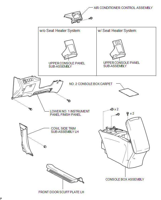
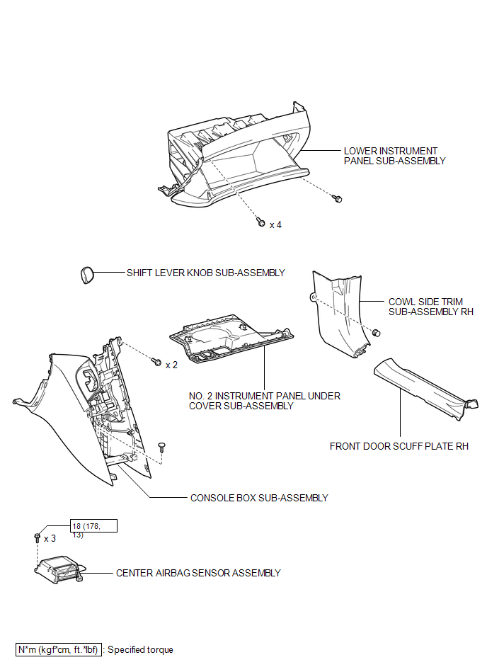
COMPONENTS
ILLUSTRATION
ILLUSTRATION

 On-vehicle Inspection
ON-VEHICLE INSPECTION
PROCEDURE
1. INSPECT CENTER AIRBAG SENSOR ASSEMBLY (VEHICLE NOT INVOLVED IN COLLISION)
(a) Perform a diagnostic system check (See page
).
2. INSPECT CENTER AIRBAG SENSOR AS ...
Other materials about Toyota Venza:
Disposal
DISPOSAL
CAUTION / NOTICE / HINT
CAUTION:
Before performing pre-disposal deployment of any SRS part, review and closely
follow all applicable environmental and hazardous material regulations. Pre-disposal
deployment may be considered hazardous material ...
Definition Of Terms
DEFINITION OF TERMS
Term
Definition
Monitor Description
Description of what the ECM monitors and how it detects malfunctions
(monitoring purpose and details).
Related DTCs
Group ...
Engine Hood Courtesy Switch Circuit
DESCRIPTION
The security courtesy switch is installed together with the hood lock. This switch
turns off when the engine hood is opened and turns on when the engine hood is closed.
WIRING DIAGRAM
PROCEDURE
1.
INSPECT HOOD LOCK AS ...

0.1177