Toyota Venza: Components
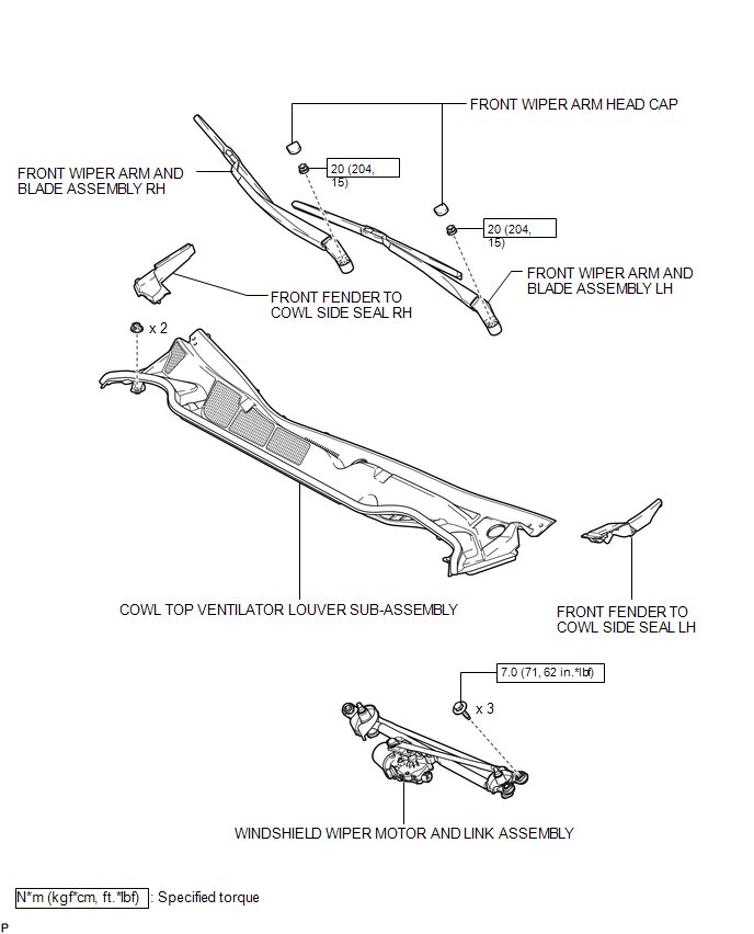
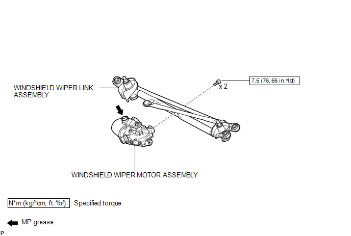
COMPONENTS
ILLUSTRATION
ILLUSTRATION

 On-vehicle Inspection
ON-VEHICLE INSPECTION
PROCEDURE
1. INSPECT WINDSHIELD WIPER MOTOR ASSEMBLY
(a) for RH Side
(1) Operate the windshield wiper motor assembly.
...
Other materials about Toyota Venza:
Glove Box Light
Components
COMPONENTS
ILLUSTRATION
Inspection
INSPECTION
PROCEDURE
1. INSPECT GLOVE BOX LIGHT ASSEMBLY
(a) Connect a positive (+) lead from the battery to terminal 1 and a
negative (-) lead to terminal 2.
...
Customize Parameters
CUSTOMIZE PARAMETERS
1. CUSTOMIZE LIGHTING SYSTEM (EXT)
HINT:
The following items can be customized.
NOTICE:
When the customer requests a change in a function, first make sure that
the function can be customized.
Be sure to make a note of ...
Installation
INSTALLATION
PROCEDURE
1. INSTALL RADIATOR ASSEMBLY
(a) Install the fan assembly with motor to the radiator with the 2 guides
at the bottom and 3 snap fits on the top.
Text in Illustration
*1
Snap fit
...

0.1585