Toyota Venza: Components
COMPONENTS
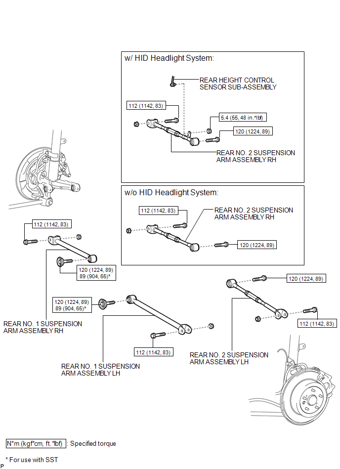
ILLUSTRATION
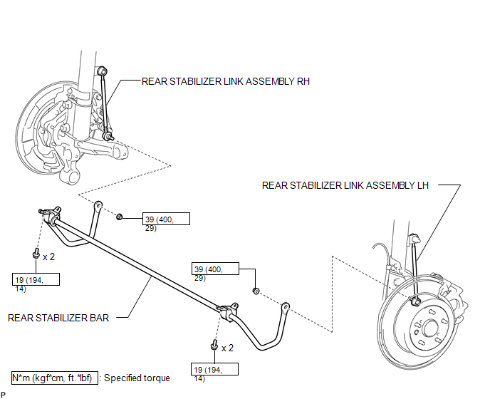
ILLUSTRATION

 Installation
INSTALLATION
PROCEDURE
1. TEMPORARILY INSTALL REAR NO. 1 SUSPENSION ARM ASSEMBLY LH
(a) Temporarily install the rear No. 1 suspension arm assembly LH to
the rear suspension member wi ...
Other materials about Toyota Venza:
All Door Entry Lock/Unlock Functions do not Operate, but Wireless Functions
Operate
DESCRIPTION
When the wireless door lock and unlock functions operate, the communication circuit
between the door lock receiver assembly and certification ECU (smart key ECU assembly)
is normal. When the entry lock and unlock functions do not operate, radi ...
Problem Symptoms Table
PROBLEM SYMPTOMS TABLE
HINT:
Use the table below to help determine the cause of problem symptoms.
If multiple suspected areas are listed, the potential causes of the symptoms
are listed in order of probability in the "Suspected Area" ...
TC and CG Terminal Circuit
DESCRIPTION
Connecting terminals TC and CG of the DLC3 causes the system to enter self-diagnostic
mode. If a malfunction is present, the MIL will blink.
HINT:
When a particular warning light remains blinking, a ground short in the wiring
of terminal TC ...

0.1399